38 electron density diagram
The electron configuration of oxygen is 1s 2 2s 2 2p 4. In O 2, therefore, we need to accommodate twelve valence electrons (six from each oxygen atom) in molecular orbitals. As you can see from the diagram, this places two electrons in antibonding orbitals. • Suppose the electron density inside a semiconductor is not uniform in space, as shown below x n(x) slope dx d n x • Since the electrons move about randomly in all directions (Brownian motion), as time goes on more electrons will move from regions of higher electron density to regions of lower electron density than the electrons that move from
The Laplacian of the Electron Density and the Lewis and VSEPR Models. While the topology of the electron density "" provides a faithful mapping of the concepts of atoms, bonds and structure, it provides no indication of maxima in corresponding to the electron pairs of the Lewis model.This model is secondary only to the atomic hypothesis itself in understanding chemical bonding and reactivity ...
Electron density diagram
The electron density is computed from the sum of squares of occupied molecular orbitals. The electron density isosurface represents the size and shape of the molecule. The electrostatic potential is the energy that a unit charge at each point in space would have due to the surrounding electrons and nuclei, which is computed by integrating the electron density divided by distance at each point ... Crystallography Produces Electron Density Maps. An X-ray crystallographic experiment produces an electron density map for the average unit cell of the protein crystal.The amino acid (or nucleotide) sequence of the crystallized polymer(s) is known in advance. The crystallographer fits the atoms of the known molecules into the electron density map, and refines the model and map to the limits of ... This diagram represents the energies of orbitals in the first 4 shells of electron density. The lowest energy shell, shell 1, contains only 1 kind of orbital. It would be filled with 2 electrons. Shell 2 has 4 orbitals and would be filled with 8 electrons. Each of the 2p orbitals has the same energy.
Electron density diagram. by CF Matta · 2002 · Cited by 100 — Contour plot of the electron density of B2H6 in the plane of the bridging hydrogen. Each hydrogen is connected to the two boron atoms by a bond ...12 pages Diagram depicting the Electron probability and contour probability, with the various nodes i.e. 1s, 2s and 3s. The diagram depicts an electron cloud with a nucleus aligned in the centre. The diagram shows the various kinds of nodal planes. The diagram depicts the probability density of an electron and the nucleus. "Dot-density" plots of electron density; Plots of radial distribution functions; Warning! This version of The Orbitron is a partial rewrite of the 2002 version of The Orbitron. It is not finished - there are still some missing images, missing videos, errors in orbital names, many typos, incorrect labels, no hybrid orbitals, and no molecular ... Understanding the Electron Charge Density Diagrams Discussion : If it were possible to conduct an experiment to determine the frequency of the electron's appearance at different points in the space surrounding the nucleus, these data could be plotted on a 3-dimensional graph.
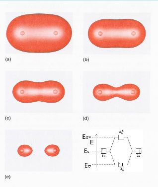
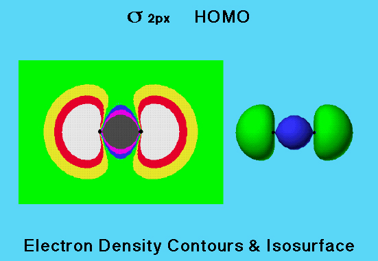
Electron density diagrams. T he elegant electron density diagrams presented here were plotted by a computer from quantum-mechanical calculations. The electron density in a cross-sectional plane passing through a molecule is plotted at right angles to that plane. These plots show the general shapes for some molecular orbitals of a homonuclear ... Don't forget to LIKE, COMMENT, and SUBSCRIBE:http://www.youtube.com/subscription_center?add_user=MoofUniversitySUPPORT MOOF UNIVERSITY:http://www.moofunivers... Download scientific diagram | 5 Contour plot of the electron density from publication: An Introduction to the Quantum Theory of Atoms in Molecules | The ... An antibonding molecular orbital has a region of zero electron density between the nuclei of the bonding atoms. A bonding molecular orbital is lower in energy than the original atomic orbitals. Consider the combination of two atomic orbitals to form a pair of molecular orbitals, designated σ2s and σ∗2sσ2s*.
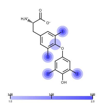
The molecular electron charge density distribution of the title compound is described accurately using the multipolar model of Hansen and Coppens. The net atomic charge and the in-crystal molecular dipole moment have been determined in order to understand the nature of inter- and intramolecular charge transfer. The study reveals the nature of intermolecular interactions including charge ... • Sigma (s) MOs have electron density in both molecular orbitals centered about the internuclear axis. • The s bonding MO is lower in energy than the s* (antibonding) MO. • The energy level diagram or MO diagram shows the energies of the orbitals in a molecule. • The total number of electrons in all atoms are placed in the MOs starting from lowest energy (s 4 Lecture 2 Pi bond (π): bonding molecular orbital -The bonding electron density lies above and below, or in front and in back of the bonding axis, with no electron directly on the bonding axis, since 2p orbitals do not have any electron density at the nucleus. In quantum chemistry, electron density or electronic density is the measure of the probability of an electron being present at an infinitesimal element of space surrounding any given point. It is a scalar quantity depending upon three spatial variables and is typically denoted as either () or ().The density is determined, through definition, by the normalised -electron wavefunction which ...
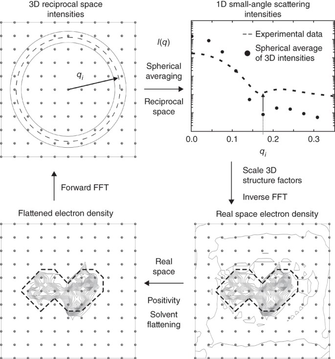
Ab Initio Electron Density Determination Directly From Solution Scattering Data Nature Methods
Also called uniform electron gas (ueg): constant non-zero density. Thomas and Fermi (1927) used fermion statistical mechanics to derive the kinetic energy for ueg as particles in a box T, V are functions of the density, while the density is a function of three spatial coordinates.
Solved Figure Figure 3d Electron Density Electron Density Chegg Com
Two atomic orbitals in phase create a larger electron density, which leads to the σ orbital. If the two 1s orbitals are not in phase, a node between them causes a jump in energy, the σ* orbital. From the diagram you can deduce the bond order, how many bonds are formed between the two atoms. For this molecule it is equal to one.

1d Electron Density Plot Along The Y Direction Of The Nanowire In The Download Scientific Diagram
required and write a partial orbital diagram. PROBLEM: Use partial orbital diagrams to describe how mixing of the atomic orbitals of the central atom(s) leads to hybrid orbitals in each of the following: (a) Methanol, CH. 3. OH (b) Sulfur tetrafluoride, SF. 4 (a) CH. 3. OH. The electron- group arrangement is tetrahedral around both the C and ...
Illustrated Glossary Of Organic Chemistry Electron Density Map
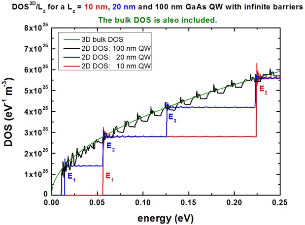
Figure 11.5 Electron concentration n is given by the area under the density of states curve up to the Fermi energy E F. The dashed curve represents the density of filled orbitals at a finite temperature. The electrons are thermally excited from region 1 to region 2. The largest number of states N can be defined when a sphere of Fermi radius k F
Solved 1 The Image At Right Shows Electron Density Chegg Com
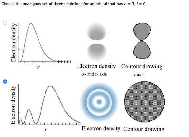
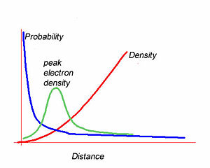
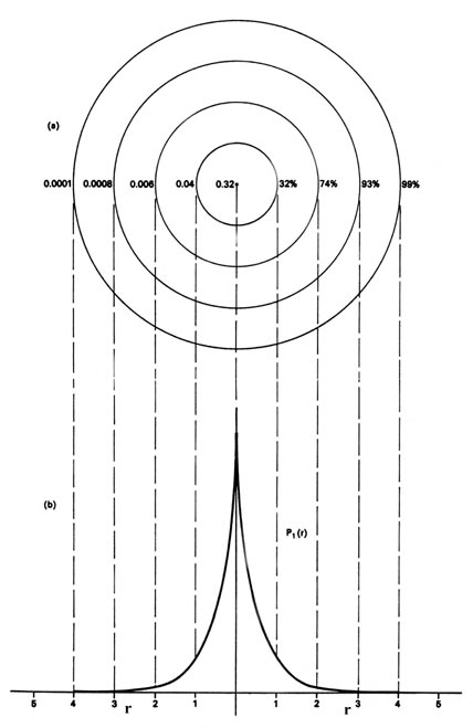
30 Sept 2021 — (b) A plot of electron probability density Ψ2 versus r shows that the electron probability density is greatest at r = 0 and falls off ...s Orbitals (l=0) · p Orbitals (l=1) · d Orbitals (l=2) · f Orbitals (l=3)
The Dependence Of Free Electron Density On The Beam Diagram Png Image Transparent Png Free Download On Seekpng
Two Dimensional Electron Gas, Quantum Wells & Semiconductor Superlattices References: ... In each diagram, the central oxide region shows the valence band edge for the oxide. On the left hand side of each diagram, the Fermi level for the metal is shown and ... a decrease in the carrier density in the channel due to the pinch-ofi phenomena.
1
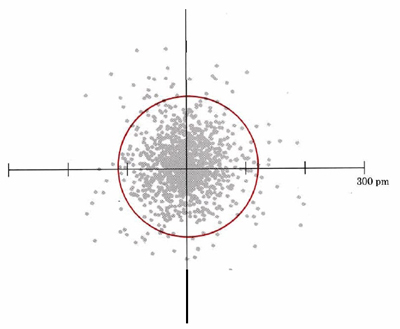
The electron cloud looks like the dot-density diagram shown in Figure 1 from Electron Waves in the Hydrogen Atom. ... Notice how the dot density diagram reveals a feature about the 2s orbital that boundary surface does not: A node divides the 2s orbital in two, a portion of the electron cloud is near the center, while another portion lies beyond the node (the circular region with no dots). At ...

Quantum Mechanical Model Part 3 Of 9 Electron Probability Density Diagrams Youtube
The electron density of a 1s orbital, on the other hand, is a maximum at the nucleus. The same diagram for the 2p density distribution is obtained for any plane which contains this axis. Thus in three dimensions the electron density would appear to be concentrated in two lobes, ...
Atomic Orbitals And Nodes Cleanenergywiki
Quantum mechanics also says that an electron can be viewed as a stationary wave, or, cloud of negative charge. According to this point of view, the electron ...

Nanomaterials Free Full Text Electron Density And Its Relation With Electronic And Optical Properties In 2d Mo W Dichalcogenides
Counting Regions of High Electron Density. Draw the Lewis structure for the molecule or ion. Count the total number of regions of high electron density (bonding and unshared electron pairs) around the central atom. Double and triple bonds count as ONE REGION OF HIGH ELECTRON DENSITY.
5 7 Electron Waves In The Hydrogen Atom Chemistry Libretexts
The two highest energy MO's are degenerate, are p-type and have no electron density associated with the hydrogen atom, ... fluorine will take a greater share of the electron density. For the energy diagram and pictorial view of the orbitals - please see below: Water: In the water molecule the highest occupied orbital, (1b 1) is non-bonding and highly localized on the oxygen atom, similar to ...
What Does Electron Density Look Like Between An Ionic Bond Quora
Electron density is a representation of the probability of finding an electron in a specific location around an atom or molecule.In general, the electron is more likely to be found in regions with high electron density. However, due to the uncertainty principle, it's not possible to identify the exact location of an electron at any instant in time.

The Plot Of Electron Density Surface Of The Monomers And The Complexes Download Scientific Diagram
Consider the 1s electron illustrated by the dot-density diagram in Figure 1 of Electron Waves in the Hydrogen Atom, for example. If the electron were actually positioned at one of these dots momentarily, it would have a definite potential energy at that moment. If we now add up the potential energy for each dot and divide by the number of dots, we obtain an average potential energy, which is a ...

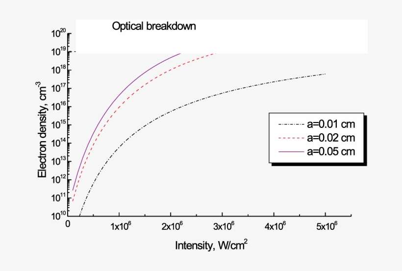
A Novel Method To Determine Electron Density By Optical Emission Spectroscopy In Low Pressure Nitrogen Plasmas Physics Of Plasmas Vol 13 No 12
As shown in the diagram below, the contribution to the electron density at a specific atom from a single electron in the BMO is given by the square of the coefficient of that atom in the BMO. For atoms 1 and 3, that is 1/4; for atom 2 it is 1/2. Since there are two electrons in
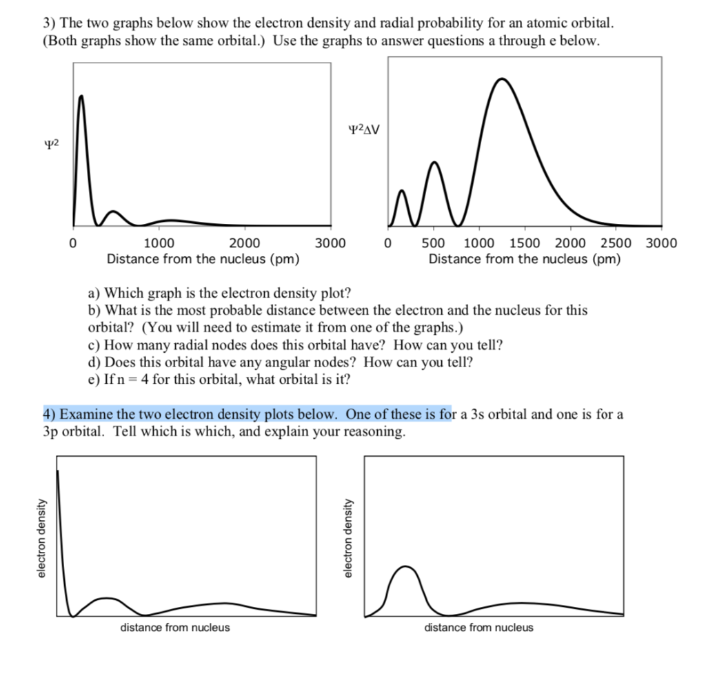
Solved 3 The Two Graphs Below Show The Electron Density And Chegg Com
Atomic orbitals: 2p electron "dot-density" This page shows representations of electron density using two-dimensional and three-dimensional electron "dot-density" diagrams. High density of dots in a region denotes high electron density. The two-dimensional plot is across a plane of a 2p orbital.
Inorganic Molecules A Visual Database
Lewis theory proposed that chemical bonds form when atoms share electron pairs. Valence bond theory describes how the orbitals of bonding species merge (overlap) to concentrate the electron density between atoms to form chemical bonds. In the case of H 2, the 1s orbitals, each containing one electron, overlap to form the H-H bond.
Uknowledge Uky Edu
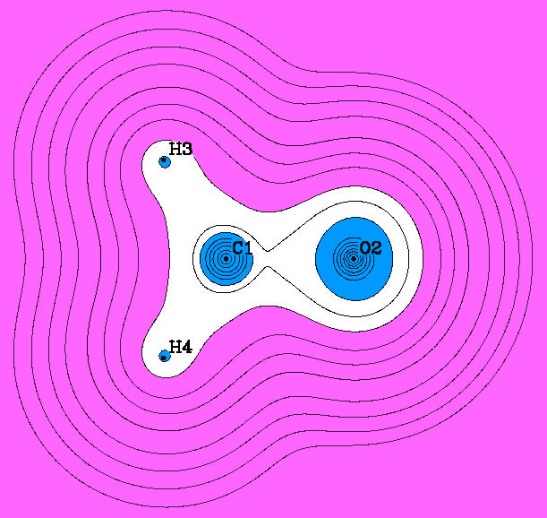
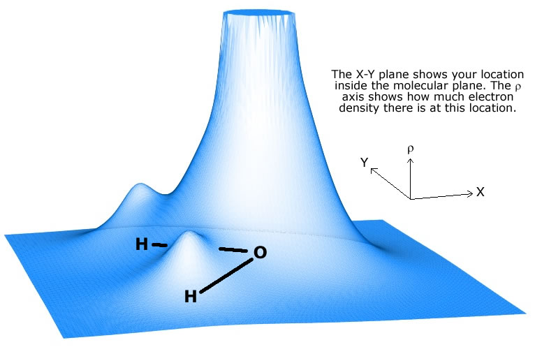
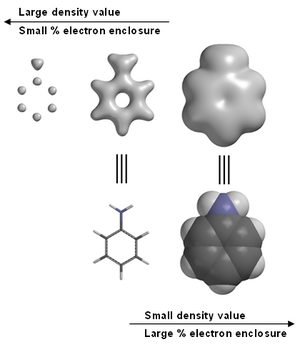
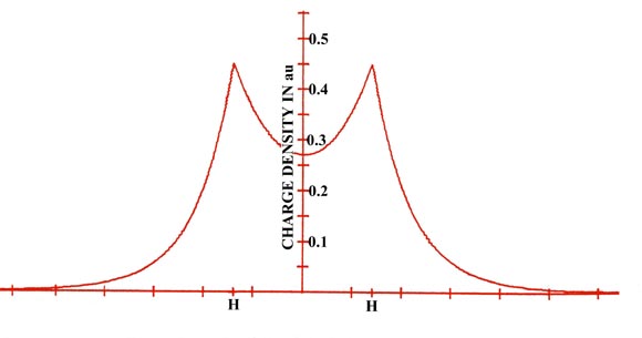
Clearly, the O nucleus attracts much more electron density than either of the H nuclei. Graphing particular values of r (rho) in 3 dimensions - Isodensity surfaces. It is also possible to construct three dimensional contour graphs. We can only look at one or two contours at a time, however, because "outer" contours tend to hide "inner" ones.

Electron Density Distribution And Crystal Structure Of 27r Alon Al9o3n7 Sciencedirect
This diagram represents the energies of orbitals in the first 4 shells of electron density. The lowest energy shell, shell 1, contains only 1 kind of orbital. It would be filled with 2 electrons. Shell 2 has 4 orbitals and would be filled with 8 electrons. Each of the 2p orbitals has the same energy.
The Hydrogen Atom The Probability Distribution Of The Hydrogen Atom
Crystallography Produces Electron Density Maps. An X-ray crystallographic experiment produces an electron density map for the average unit cell of the protein crystal.The amino acid (or nucleotide) sequence of the crystallized polymer(s) is known in advance. The crystallographer fits the atoms of the known molecules into the electron density map, and refines the model and map to the limits of ...

Pdb 101 Learn Guide To Understanding Pdb Data Structure Factors And Electron Density
The electron density is computed from the sum of squares of occupied molecular orbitals. The electron density isosurface represents the size and shape of the molecule. The electrostatic potential is the energy that a unit charge at each point in space would have due to the surrounding electrons and nuclei, which is computed by integrating the electron density divided by distance at each point ...
1d Dos In A Qw
Visualizing Electron Density Openeye Python Cookbook Voct 2019
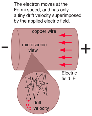
Ohm S Law Microscopic View
Mapping Electron Density Image Eurekalert Science News Releases
Electron Density Learning Of Non Covalent Systems Chemical Science Rsc Publishing Doi 10 1039 C9sc02696g
Iucr Electron Density Representation

Rcsb Protein Data Bank Visualize Electron Density Maps For Bound Ligands Facebook
Quimica Ufpr Br

Protein Structural Ensembles Are Revealed By Redefining X Ray Electron Density Noise Pnas
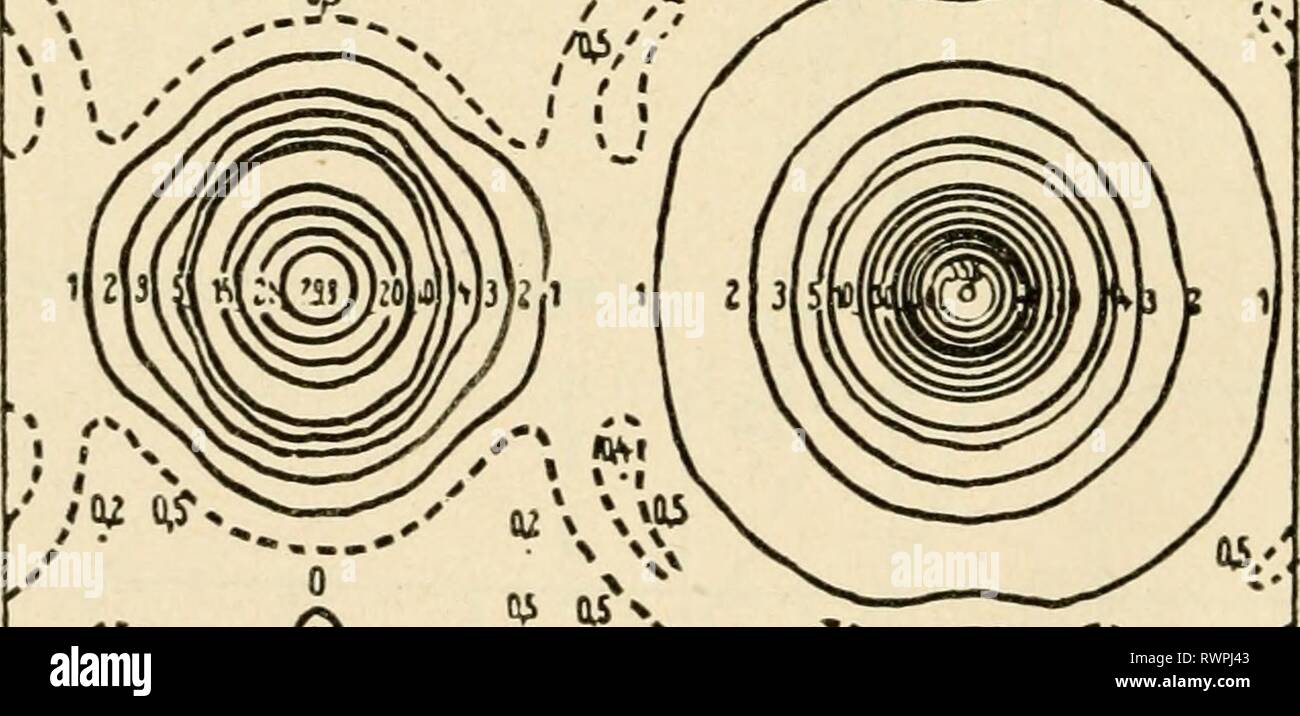
The Electron Microscope Its Development The Electron Microscope Its Development Present Performance And Future Possibilities Electronmicrosco00gabo Year 1948 Ii V 0 0 0 O Fig 48 Electron Density

Electron Density Distributions In Saturn S Ionosphere Persoon 2019 Geophysical Research Letters Wiley Online Library

Comparison Of Superdarn Peak Electron Density Estimates Based On Elevation Angle Measurements To Ionosonde And Incoherent Scatter Radar Measurements Springerlink
Roco Electron Density Universal Features
The Orbitron 6p Atomic Orbitals Dot Density
Roco Electron Density Graphs
Electron Density Wikipedia

Crystallography Structural Resolution
The Chemical Bond Introduction
Comments
Post a Comment