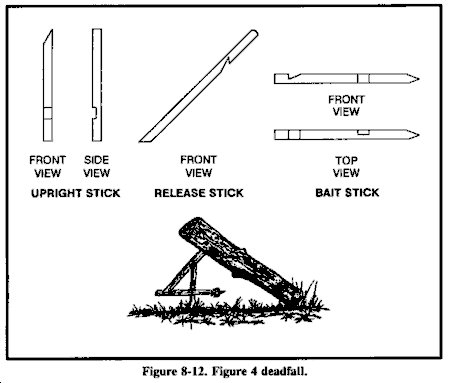
43 figure 4 trap diagram
Figure 5. Upper diagram depicts Franck-Condon factors f ν vs vibrational quantum number ν for the interaction potential Rb1 and fixed n = 55, trapping frequency ν trap = 40 kHz. Lower diagram shows the accumulated contribution of vibrational bound states vs ν for δ = 2 π × 3 MHz. Reuse & Permissions Figure 4c shows the energy band diagram under the V GS negative sweeping at V DS = 2.0 V and V GS = − 1.0 V in the n-FBFET. This indicates that the potential barrier heights are varied by the ...
The concept diagram of the micro-chip is shown in Fig. 6. Two fibers are fixed by fiber arrays (FA). The spacing of the waveguide end is 300 μ m, and the transverse offset is 9.7 μ m. The size of chip is 4 mm × 8 mm × 1 mm. During the experiment, the liquid sample containing microspheres is imported into the microgroove between the FA.
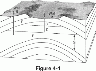
Figure 4 trap diagram
Understanding the atomic nature of reactive sites and surface traps is a key enabling step towards optimizing chemical conversion at semiconductor-liquid junctions. 1-3 The recent development of operando analysis tools has provided deep insights into the operation of specific semiconductor electrodes for solar-driven H 2 production via water splitting. 4-7 However, each material brings a ... Figure 4. Plots represent the phase space trajectories of a single particle inside an optical trap for (a) 40 nm, (b) 0.4 μm, and (c) 4 μm particle size at 10 mW average power under both cw and pulsed excitations. Red and black vectors correspond to cw and pulsed excitations, respectively. Reuse & Permissions The variation of the electron trap depth Bi R (0 / − 1) is shown mainly due to the shift of the conduction band, while the hole trap level Bi R (+ 1 / 0) shows the correlation with the shortest R - O bond length in hosts. Based on the defect level diagram from the first-principles calculation, the transition types of excitation and emission ...
Figure 4 trap diagram. Jun 9, 2013 - Here is a diagram of a one-stick figure-4 deadfall trap. Jun 18, 2019 — In its simplest form, a figure 4 trap starts with just three sticks, each about 8 inches long and 1 1/2 inches in diameter. From there, each ... (8) All trap distances from vents as represented in the figures are in compliance with 248 CMR 10.16 (1 l)(a): Table 1. (9) See 248 CMR 10.13 before installation of any special hazardous waste system, Figure 16. (10) Figures are not to scale. FIGURE 1: Illustration of Boiler Blowoff Tank. Click to view image. FIGURE 2: Illustration of Maximum Distance from Trap to Vent in Compliance with 248 ... Figure 4 (a) Clock-transition frequency shift as a function of applied trap rf power where the solid line is a linear fit to the data. (b) Measured clock-transition frequency as a function of applied static magnetic-field offset from 146.094 G, measured at P rf = 392 mW.
Figure 6 (a) Example measurement of the D 2 light shift by resonantly heating the atom out of the trap with a probe beam, taken at three different tweezer powers (3.7 mW, 3.1 mW, 1.9 mW) at 615.87 nm. (b) Frequency shifts of the admixed hyperfine levels of 3 2 P 3 / 2 state as a function of the ground state trap depth in the absence of a ... How to Make a Figure 4 Deadfall: This deadfall is used to catch a mice and squirrels and anything else small. The bait is attached to the end of the pointed ... Figure 4. The steady state phonon occupation as a function of the Rabi frequency Ω. The black line and black dashed lines are exact numerical results and our analytic predictions in the SSC regime, while the blue dot-dashed represents the analytic results predicted in the WSC regime. The other parameters used are n 0 = 4, η = 0.1, γ = 0.1νν. Jul 17, 2013 — The figure-four deadfall is often the first trap illustrated in the trapping chapter of your handy pocket survival guide.
The phase diagram of the game process is shown in Figure 4. (3) ... The game phase diagram is shown in Figure 7. (5) ... will decrease. Second, too many rewards will easily make paper-making enterprises fall into "reward invalid" trap. After receiving the reward, the paper-making enterprises do not implement any effective actions to reduce ... An example of a typical plumbing diagram is shown is FIGURE 1. 11302020 Basement bathroom floor plans page 4 basement bathroom rough in pipe basement bathroom layout bigger than help with basement rough in pics included identifying basement bathroom rough in. That way you have enough space to clear the P-trap. Steam trap is a device used to discharge condensate and non condensable gases with a negligible consumption or loss of live steam. Need fresh looking process and instrument diagram symbols for your design? These process and instrument diagram symbols are a cinch to pop in. Figure 4(d) qualitatively summarizes this in a comprehensive energy band diagram. The band diagram elucidates that with the increase of WSe 2 thickness, the effective energy gap decreases, and the spatial energy location of interface traps and thereby Fermi level modulates from valence band side to the conduction band side, resulting in the ...
Solved Which Layer In Figure 4 1 Forms The Cap Rock For The Chegg Com
Table 1 demonstrates the component values which were put to use for the schematic in Figure 4. There seemed to be no sense in carrying out simulations at or above 10 MHz mainly because laboratory tests were essentially conducted as a start-up, and 1 MHz was the leading frequency where a notch filter was needed to be applied.

The Flex Option Offense Trap Option
(b) Venting of Fixture Drain below Trap. 1. The vent pipe openings from a soil or waste pipe, except for toilets and similar fixtures, shall not be below the top weir of the trap. 2. An exception to 248 CMR 10.16(12)(b) will be permitted if the following requirements are satisfied: a. The fixture has a flat bottom with a minimum area of 144 square inches.

Capillary Based And Stokes Based Trapping Of Serial Sections For Scalable 3d Em Connectomics Eneuro
Figure 1. Phase diagram and morphologies beyond the supersolid droplet regime. (a) The left-hand side shows the N − a s phase diagram for trap frequencies ω / 2 π = (125, 125, 250) Hz.The right-hand side shows 2D density cuts n (x, y, 0) at relevant points in the phase diagram, shown by the corresponding markers. The density distributions for a specific marker are ordered in atom number ...
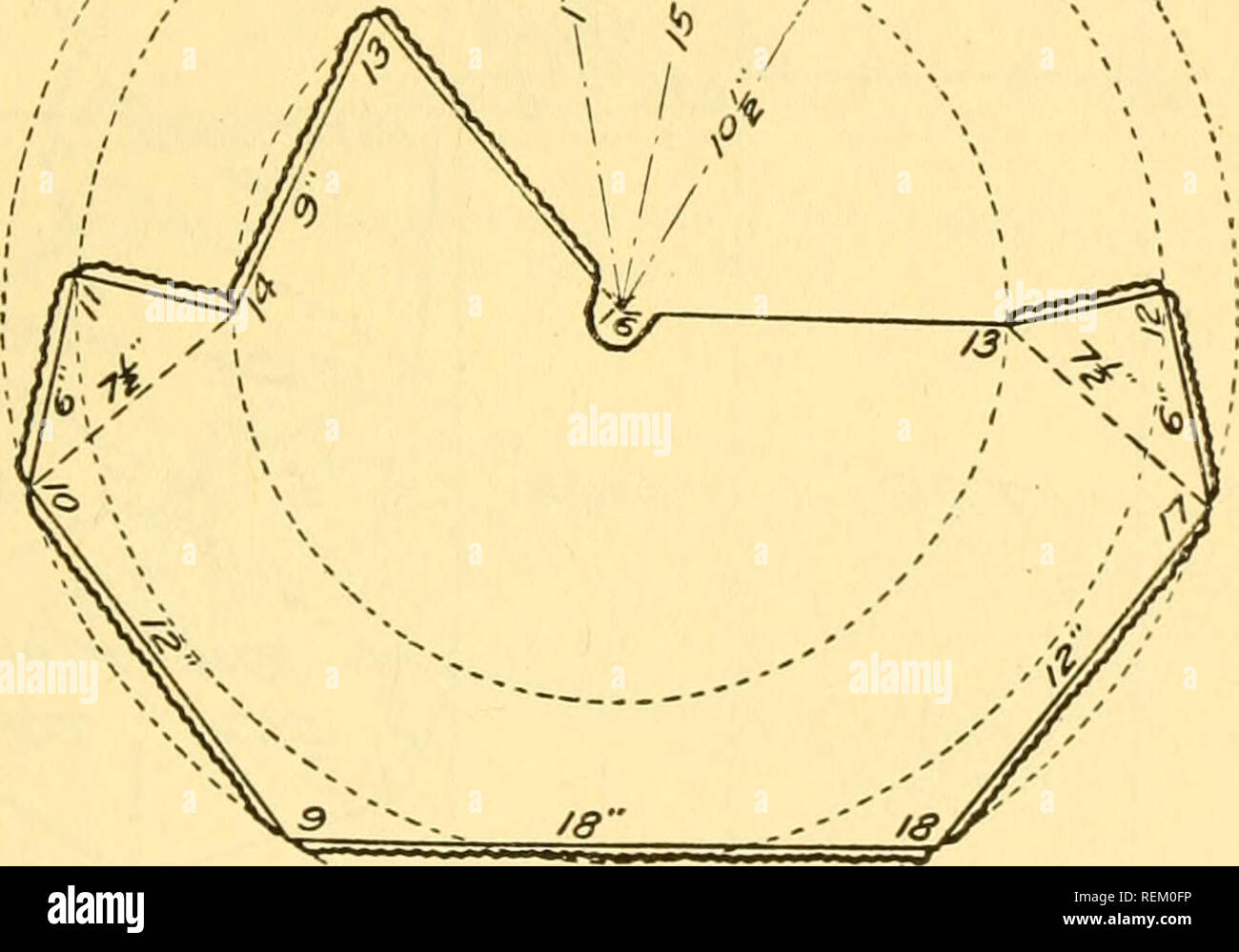
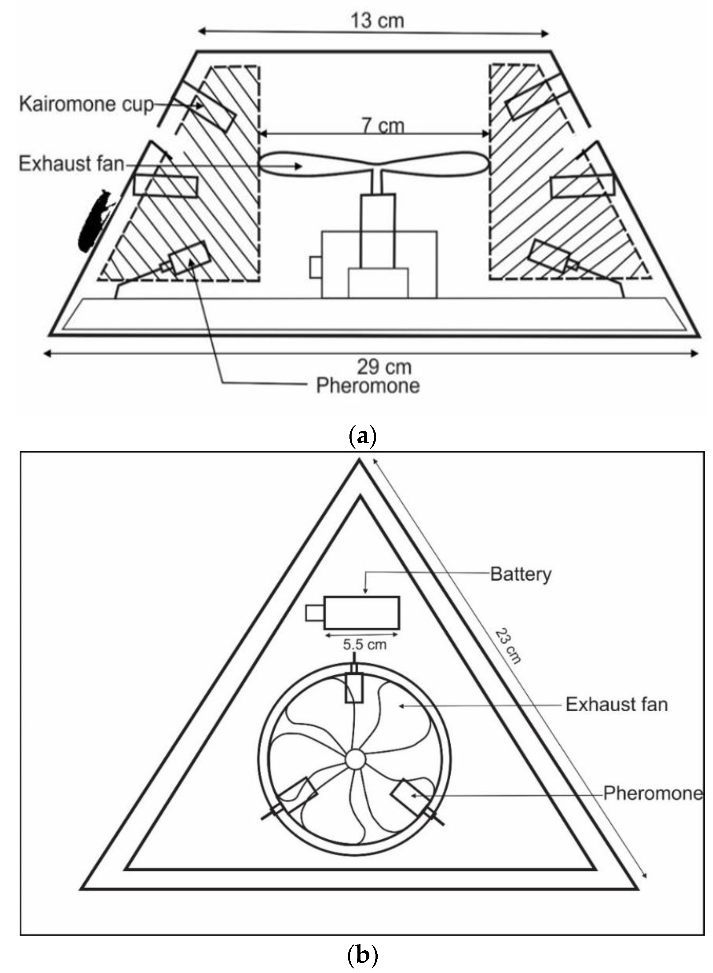
Circular Agriculture 11 The Top And Sides Of The Trap Fig 7 Shows How All The I Arts Of A Trap Having The Above Dimensions May Be Cut From A Piece Of
As shown in Figure 3e, the work function was reduced by 0.1 eV from 4.83 to 4.73 eV by the treatment. The work function change reflects a Fermi level ( E F ) shift toward the CBM, which is consistent with the removal of electron traps by the UVNOI process.

Entomological Classics The Light Trap Don T Forget The Roundabouts
To capture neurons that were active during a peripheral immune challenge, we used transgenic targeted-recombination-in-active-populations (TRAP) mice (DeNardo et al., 2019; Guenthner et al., 2013) (Figure 1A).These mice express iCreER T2 under the control of an activity-dependent c-Fos promoter (Fos TRAP mice), which serves as an indicator of neuronal activity.

Alignment Of The Optical Trap Shown Is A Schematic Illustration Of A Download Scientific Diagram
Figure 6: Schematic diagram of orbital ion trajectories in an Orbitrap and example resulting mass spectrum. Credit: Adapted from 2, reproduced under the Creative Commons Attribution 4.0 International license. The axial electric field caused by the special conical shape of electrodes pushes ions toward the widest part of the trap.

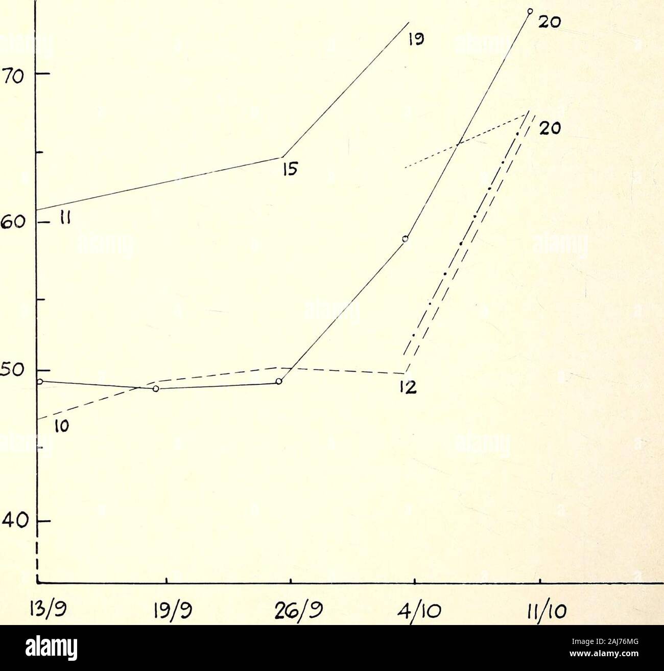
Mean Se Of The Number Of Mango Weevils Captured By The Traps And Download Scientific Diagram
To clean the fiber channels and the circular hole above the trap region of the 3D printed device, a cleaning chip was designed as shown in the Figure S1. The cleaning chip applies pressure via ...
Rabbit Deadfall
The comparison of the experimental SPV transients shown in Figure 4 with the simulated transients in Figures 6A and 6B demonstrates that the characteristic features in the SPV transients can be very well reproduced by the model and therefore account for the interplay between trap passivation and hole transfer rate. Thus, the simulation results ...

Stationary States In The Rotating Trap Characterised By The Velocity Download Scientific Diagram
Figure-4 Deadfall · A rock or other weight rests on the end of the diagonal stick. · The diagonal stick rests on and pivots on the vertical stick at "C". · The ...
Paiute Deadfall
Figure 4. Timing diagram for simultaneous cooling of Na and Cs. Parameters are described in the main text. The last row indicates the trap depth for Na (taking into account the effect of gravity). The corresponding values for Cs are 164 μ K at the beginning and 0.5 μ K at the end of the sequence. Reuse & Permissions

How To Make A Figure 4 Deadfall 4 Steps Instructables
There is one thing a causal diagram cannot abide, and that is cycles. That is, you shouldn't be able to start at one variable, follow down the path of the arrows, and end up back where you started. There are two examples of graphs with cycles below in Figure 7.3. In the first one, you can go A → B → C → A.
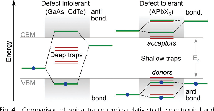
Pdf It S A Trap On The Nature Of Localised States And Charge Trapping In Lead Halide Perovskites Semantic Scholar
Figure 4-4. Sequence diagram of simulation flow with Dapr building blocks. ... The Traffic Control sample application is a microservices application that simulates a highway speed trap. The application uses several Dapr building blocks to make it robust and cloud-native. The domain is kept simple to keep the focus on Dapr.

Characterization Of Vector Communities And Biting Behavior In South Sulawesi With Host Decoy Traps And Human Landing Catches Parasites Vectors Full Text
Figure 3. Phase diagram. Green curve is the Glaso (1980) bubble point and red dew point curve of England (2002). At reservoir pressure of 2000 psi, any incoming fluid between 400 scf/bbl and 60,000 scf/bbl will form a dual phase trap. Whether the gas phase, or the oil/condensate phase is preserved depends on the seal capacity and trap closure.
Figure 4
In Figure 8, when we change the ratio among α 1, α 2, α 3, and α 4, the peak intensity of the corresponding optical trap changes. In Figure 8A, α 1, α 2, α 3, and α 4 are 2.6, 2.6, 1, and 1, respectively. We keep α 1 and α 3 unchanged and reduce α 2 to 1.3, and α 4 to 0.5. The corresponding peak intensities decrease, as shown in ...

20 Trapping Ideas Survival Bushcraft Wilderness Survival
Figure 4. Projected pair-momentum distribution n pair proj (Q) as a function of the pair momentum Q (in units of k F) for different temperatures. The left panels show results at unitarity for polarizations (n ↑ − n ↓) / n = 0.40 (a) and 0.50 (c), while the right panels correspond to (k F a F) − 1 = − 0.5 and polarizations 0.25 (b) and ...

Bcgmcgsgi50ehm
Figure Figure5e 5 e shows that the trap stiffness of the PS-silica microsphere trapped by the GB and RPB is enhanced compared to that of the PS microsphere shown in Fig. 4 i. Qualitatively, trap stiffness for the uniform PS microsphere, trapped by the GB and the RPB are about 0.33 and 0.61 pN nm-1, respectively, while the corresponding values ...
Wideband Infrared Trap Detector Based Upon Doped Silicon Photocurrent Devices
The variation of the electron trap depth Bi R (0 / − 1) is shown mainly due to the shift of the conduction band, while the hole trap level Bi R (+ 1 / 0) shows the correlation with the shortest R - O bond length in hosts. Based on the defect level diagram from the first-principles calculation, the transition types of excitation and emission ...
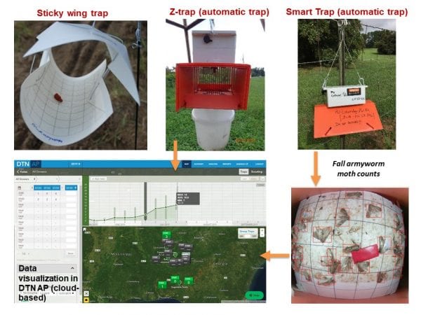
Modern Insect Pest Monitoring Using Automatic Traps Alabama Cooperative Extension System
Figure 4. Plots represent the phase space trajectories of a single particle inside an optical trap for (a) 40 nm, (b) 0.4 μm, and (c) 4 μm particle size at 10 mW average power under both cw and pulsed excitations. Red and black vectors correspond to cw and pulsed excitations, respectively. Reuse & Permissions

Georgia Bushcraft Llc Have You Made A Figure 4 Trap Or Deadfall These Are Great Practice In Carving And Notching Photo Textbook Survival Georgiabushcraft Bushcraft Bushcrafts Bushcrafters Bushcrafters Bushcraftskills Bushcraft101
Understanding the atomic nature of reactive sites and surface traps is a key enabling step towards optimizing chemical conversion at semiconductor-liquid junctions. 1-3 The recent development of operando analysis tools has provided deep insights into the operation of specific semiconductor electrodes for solar-driven H 2 production via water splitting. 4-7 However, each material brings a ...

Survival Skills The Figure 4 Deadfall
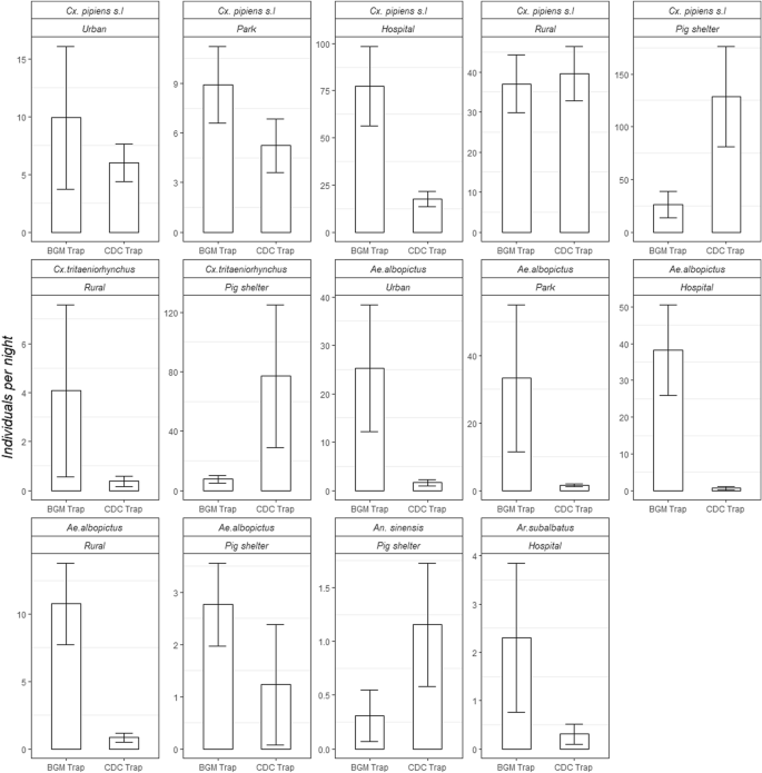
Field Evaluation Of Two Mosquito Traps In Zhejiang Province China Scientific Reports

140 Survival Traps Triggers Ideas Survival Survival Skills Wilderness Survival

Cross Section Of The Front Of The Trap All Measurements In Millimetres Download Scientific Diagram
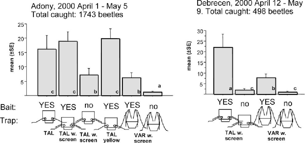
Pdf Effectiveness Of Different Trap Design In Mass Trapping Of Bothynoderes Punctiventris Germar Semantic Scholar
Hybrid Femtosecond Laser Fabrication Of A Size Tunable Microtrap Chip With A High Trapping Retention Rate

Advanced Powered Sliding Or Guillotine Door Trap System For Cage Or Corral Type Animal Traps Diagram Schematic And Image 05
2
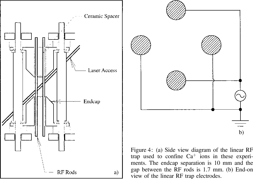
Pdf The Los Alamos Trapped Ion Quantum Computer Experiment Semantic Scholar
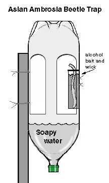
Ambrosia Beetle Pests Of Nursery And Landscape Trees Nc State Extension Publications
Insects Free Full Text Changes In Shape Texture And Airflow Improve Efficiency Of Monitoring Traps For Tribolium Castaneum Coleoptera Tenebrionidae

How To Make A Figure 4 Deadfall Trap Deadfall Trap In Action Catching Mice Youtube
The Victorian Naturalist 20 M 100 5 Figure 4 Trapping Grid Home Ranges Indicated By Continuous Lines Dots Are Trapsites 3 Traps Per Site Crosses Mark Calculated Centres Of Activity 100 5 Meansanimal
Making A Figure 4 Deadfall Outdoorhub

Pin On Survival

The Urban Aboriginal Theurbanabo Com Primitive Technology Aboriginal Living Skills Study Practice

A Bode Diagram Of Trap Filter Transfer Function Y 21 B Bode Diagram Of Download Scientific Diagram
I Trap A Method To Identify Transcriptional Regulator Activated Promoters Bmc Infectious Diseases Full Text

How To Make A Figure 4 Deadfall Trap
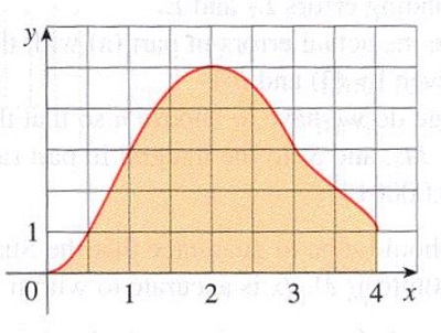
Estimate The Area Under The Graph In The Figure By Using A The Trapezoidal Rule B The Midpoint Rule And C Simpson S Rule Each With N 4 Trap 4 Mid 4 Simpson 4 Study Com

The Tbrii 2 Trap Is Stable And Retains Full Activity In Human Serum Download Scientific Diagram

Survival Trapping 4 Easy Traps To Learn Recoil Offgrid
Three Dimensional Imaging Of Trapped Cold Atoms With A Light Field Microscope
2
Comments
Post a Comment