42 traffic signal wiring diagram
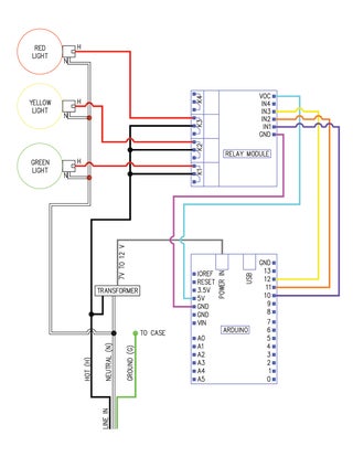
Most engineering drawings include the wiring diagram for how detectors are associated to phases. Signal timing settings such as the passage time, delay, extend, and other related parameters are described in more detail in Chapter 5. The size and location of detectors is an important element in traffic signal design. Below is a wiring diagram for the traffic signal. Hopefully this is pretty clear what gets wired to what. Add Tip Ask Question Comment Download. Step 3: The Brains. Above is a photo of the Arduino Uno and the relay module with the wiring between the two attached. I only had male to male jumpers, so I used a Molex connector and my mad soldering skills to make a connector (second photo). It is ...
The schedules and wiring diagrams in Fig. TS-6 are shown in greater detail in. Figures TS-7 through 7-12. All symbols used in the design of traffic signals ...37 pages

Traffic signal wiring diagram
TRAFFIC SIGNAL DESIGN HANDBOOK. Bureau of Maintenance and Operations . Publication 149 . October 14, 2010 (May, 2013 Update) Field Wiring Diagram Interconnect Layouts For Information Only Sheet(s) Utilities 8 Title Sheet Title Sheet -The title sheet is required for all traffic signal plans. It includes information such as the title block, project location, governing specifications, etc. 9 Title Sheet -Plan Preparation Certification Note Below is a wiring diagram for the traffic signal. Hopefully this is pretty clear what gets wired to what. Above is a photo of the Arduino Uno and the relay ...
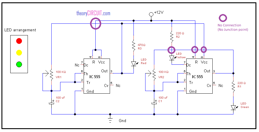
Traffic signal wiring diagram. Four Way Traffic Light Controller Circuit Using 555 Timer Ic And Cd4017 Electroduino. Simple four way traffic light circuit project diagram using 555 lights controller sigmatone two system 8051 digital logic design control 20 step schematic signal arduino automatic pic16f877a microcontroller 6 plc ladder interactive toy schematics com based 4 by emergency 3 density presentation topic one ... 1 May 2014 — Wiring diagram. Phasing diagram. Detection chart. Signal support mounted signs. Traffic signal interconnect including splicing details and ... Traffic Light Signal Circuit Diagram Traffic Lights Wiring Ne555 Traffic Light Circuit Kit Analog Signal Simulator Module Workshop Weekend Archaic Digital Design Traffic Lights Circuit Implemented On Multimedia Logic Download Four Way Traffic Light System Using 8051 Microcontroller And 7 Traffic Lights Using Arduino Uno Arduino Project Hub ... Traffic Signals Circuit Diagram. By Margaret Byrd | April 1, 2018. 0 Comment. Simple four way traffic light circuit lights controller sigmatone using ic 555 diagram the language for model cars or a with an attiny85 signal control davidtsai. Simple Four Way Traffic Light Circuit Traffic Lights Controller Light Using Tranistors Simple Traffic Light Controller Sigmatone Traffic Light Circuit ...
The analog signal is first applied to the ‘sample‘ block where it is sampled at a specific sampling frequency.The sample amplitude value is maintained and held in the ‘ hold‘ block. It is an analog value. The hold sample is quantized into discrete value by the ‘quantize‘ block.At last, the ‘encoder‘ converts the discrete amplitude into a binary number. No HUB required. Internal temperature sensor for overheating protection. Shelly EM can automatically turn off the whole circuit if consumption or energy (prepaid energy option) reaches the set limit. 21 Apr 2010 — installation of traffic signals in the City of Puyallup. ... schematic wiring diagram shall include, but not be limited to the following:. PHASE AT HIGH SPEED TRAFFIC SIGNALS 6. Performing Organization Code 7. Author(s) Srinivasa R. Sunkari, Carroll J. Messer, Ricky T. Parker, and Hassan A. Charara 8. Performing Organization Report No. Report 0-4260-3 10. Work Unit No. (TRAIS) 9. Performing Organization Name and Address Texas Transportation Institute The Texas A&M University System College Station, Texas 77843-3135 11. Contract ...
CCTV (Closed-circuit television) diagram is used to depict a system of video monitoring. The CCTV diagram provides video cameras placement strategy. CCTV diagram should include the scheme of strategic placement of video cameras, which capture and transmit videos to either a private network of monitors for real-time viewing or to a video recorder for later reference. (d) SCATS® is the name of the Sydney Co-ordinated Adaptive Traffic Signal system, registered by Transport for New South Wales. .2 Documents referenced in this Part are listed below: (a) AS 2276 Cables for Traffic Signal Installations (b) AS 2339 Traffic Signal Posts and Attachments (c) AS 3000 Electrical Installations Traffic signal and flashing beacon control equipment normally is designed to operate on a 120-volt AC circuit. A 120-volt or 240-volt circuit is normally used for highway lighting circuits. For very large lighting circuits, a 480-volt circuit may be required. what I do at my job x3
Pdf Solutions For Traffic Lights Intersections Control
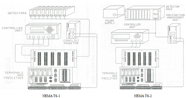
Econolite Ts2 Cabinet Wiring Diagram. NEMA Traffic Signal Controller Cabinets NEMA TS2 Specifications (DOC) English controller cabinets designed for ultimate ease in configuration and installation. Econolite offers an extensive, high quality line of NEMA TS1 and TS2. Econolite Control Products Inc. provides this manual for its licensees TS2 ...
2
Traffic Signal Plan Details. Notes; o Added new note to "enable detector switching to extend φ4 & φ8 with φ3 & φ7 loops once left turn phases are exhausted" 11. Traffic Signal Plan Details "Grouped" elements for diagrams on drawing; 13. Traffic Signal Plan Details. Added Uninterruptible Power Supply and UPS Cable to Wiring Diagram ...
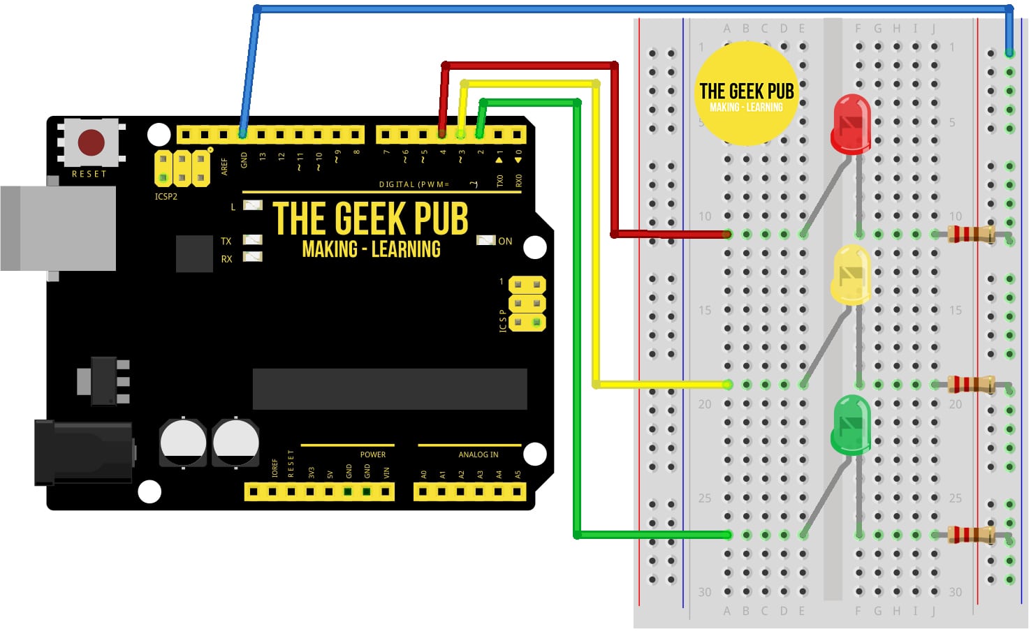
Arduino Traffic Light Project The Geek Pub
Signal Indication Burned Out Shorted or Open Field Wiring Output side of load Switch shorted Bad transfer Flash relay Bad Load Switch, EPAC, BIU in TS2 Controller found the fault, Police Flash Switch,TS2 Check Frame Faults This is a NON Latching Fault (can be set to latching) The signal will return to normal operation when 24 vdc isrestored Power

Wiring Diagram Of Traffic Light Using Magnetic Contactor Youtube
schematic wiring diagram lighting aluminum transformer base part no. tb-17 (breakaway) drawing number drawing number drawing number ... traffic signal mast arm 15', 20' & 25' with clamp detail for "k" standard traffic signal standard steel and arm details for electrical signs

Fhwa Railroad Highway Grade Crossing Handbook 4 Identification Of Alternatives
between traffic signal timing and transportation policy and addresses maintenance and operations of traffic signals. It represents a synthesis of traffic signal timing concepts and their application and focuses on the use of detection, related timing parameters, and resulting effects to users at the intersection.
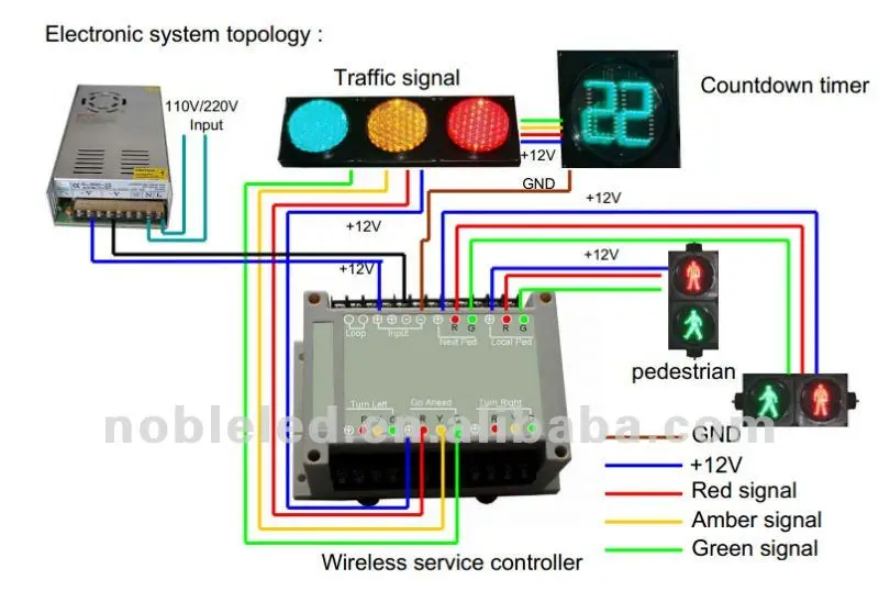
300mm Roadway Safty Dynamic Pedestrian Traffic Light Buy Pedestrian Traffic Light And Countdwon Timer Led Pedestrian Light Traffic Signal Lights Product On Alibaba Com
hi i have a 1966 delta 88 .car was broken into and destroyed the steering column. i bought the aftermarket turn signal assembly any one have a wiring diagram for car . thank you #163. emelian (friday, 25 september 2020 08:33)
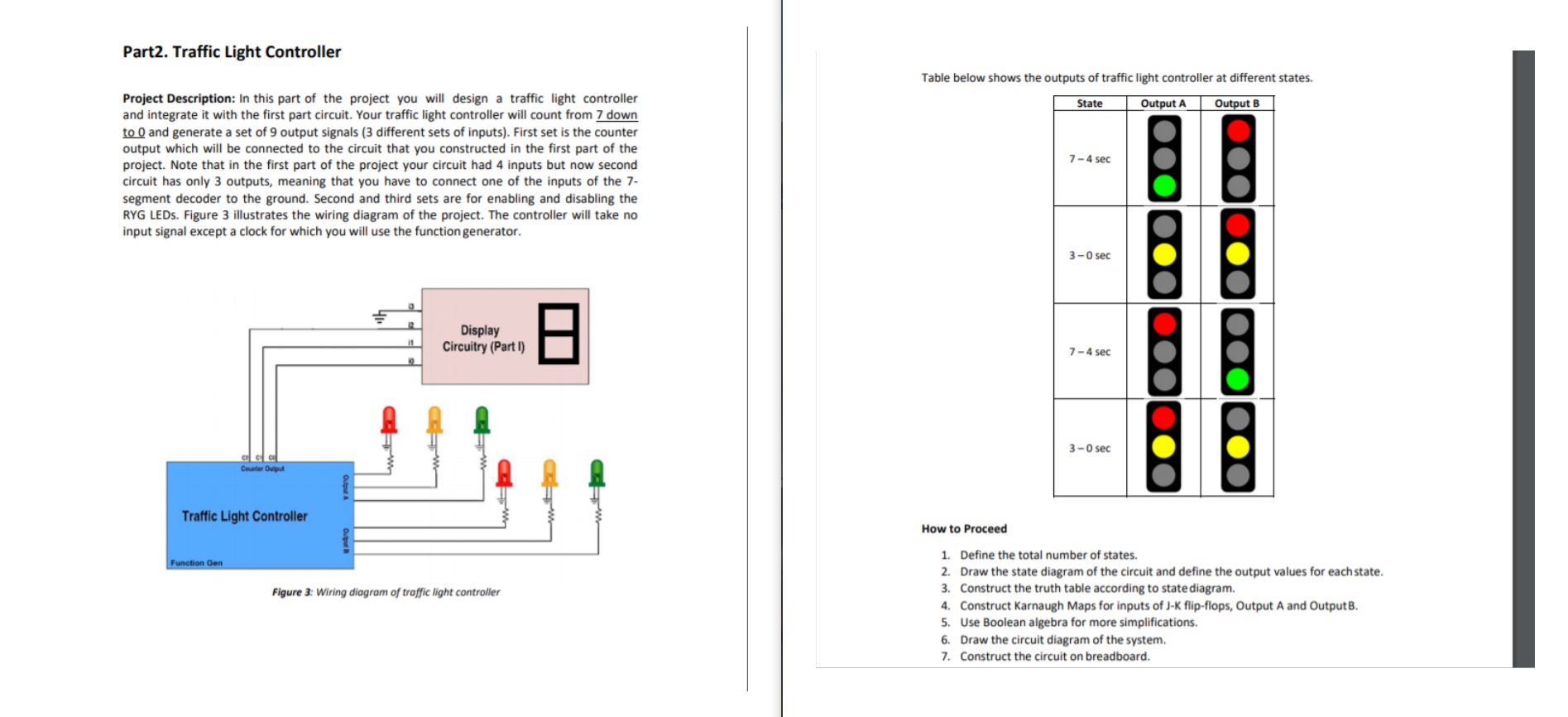
Solved Table Below Shows The Outputs Of Traffic Light Chegg Com
Switch setting 3, wiring diagram A. 4. Green to flashing Green to Red and back to Green. Use as Arrow to flashing Arrow to Red back. to Green. Switch setting 4, wiring diagram B. 5. Hand-man countdown crosswalk signal only. Switch setting 5, wiring diagram F. 6. Single light flashing, adjustable rate. Switch setting 17, wiring diagram C. 7.
Manual Button Controls For Traffic Light Diy Home Improvement Forum
Please subscribe and share for more videos.NEGATIVE TRIGGER RELAY WIRING DIAGRAMhttps://youtu.be/wuXjVleozXwPOSITIVE TRIGGER RELAY WIRING DIAGRAMhttps://yout...

Circuit Desolator Traffic Light Circuit Based On 4017
Historical - Signals and Lighting Standard Drawings. This page provides a PDF copy of the Traffic Engineering Signals and Lighting Historical Standard Drawings. The historical standard drawings are listed first by standard drawing number and then by date signed. The date signed references the date the standard became effective.
Traffic Light Circuit Diagram Using 555 Timer Ic
Null modem is a communication method to directly connect two DTEs (computer, terminal, printer, etc.) using an RS-232 serial cable.The name stems from the historical use of RS-232 cables to connect two teleprinter devices or two modems in order to communicate with one another; null modem communication refers to using a crossed-over RS-232 cable to connect the teleprinters directly to one ...

Traffic Light Diagram Using Time Relay Magnetic Contactor Wide Way Optoelectronics
of the highway traffic signals and railroad personnel. The goal of this guide is to provide a comprehensive discussion regarding the state-of-the-practice in preemption of traffic signals with nearby highway-rail intersections. Much of what is presented in this guide has been adapted from ITE's 1997 Recommended Practice.
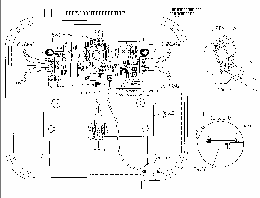
Figure 15 From Interfacing Accessible Pedestrian Signals Aps With Traffic Signal Control Equipment Semantic Scholar
for signal heads typical wiring turn from v4. to v2. deleted the words left wiring schematic. added 150 a4h rev. 11-1-11: revised typical 8 phase details. phase and typical loop numbering-modified typical loop number-4 v1, v2, v5, p1, and p2. rev. 7-29-04: modified details 7 conductor cable. and 5-section heads to rev. 12-16-03: change 3-section 2-14-92 t-sg-12 s n a p p t s n a p p t 12 / 2 0 ...

Using Time Delay Relays To Cycle A Traffic Signal
Traffic Signal Design Manual and Technical Specifications 3 of 55 4/21/2010 II. SIGNAL WARRANT ANALYSIS, ENGINEERING STUDY, and DESIGN PROCESS The following guidelines describe the typical process for the determination and basis of design for a typical traffic signal within the City of Puyallup. The Signal Designer shall set up a meeting with the
2
B. Two (2) paper copies and one electronic copy of traffic signal controller cabinet schematic wiring diagrams shall be submitted at the time the controllers are delivered for testing, or if ordered by the Engineer, prior to purchase. This diagram shall show the location and phasing of the intersection; list of all equipment installed in each ...
Traffic Light Circuit Using Ic 555
(a) Traffic Signal Drawings;. (b) Signal Duct Layout Drawings;. (c) Site Wiring Diagram;. (d) Cable Connection Schedule;. (e) Detector Wiring Chart;.13 pages
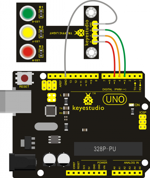
Ks0310 Keyestudio Traffic Light Module Black And Eco Friendly Keyestudio Wiki
Like. Comment & Subcribe :)'DO IT AT YOUR OWN RISK'Follow me onFacebook: MotoFix PHSEND ME STUFF?FOR SPONSORSHIP?Business inquiries!Email me: motofixph@gmail...

Traffic Signal Stop Light Wiring With Arduino Controller 7 Steps With Pictures Instructables
Traffic Signal - Annual Inspection with Overall Score (to be in ITS Collector App) 1. General. 7/8/2021. Traffic Signal Final Inspection Form (2019 Spec) Traffic Signal Final Inspection Form (2019 Spec) Revised-05-01-2019.
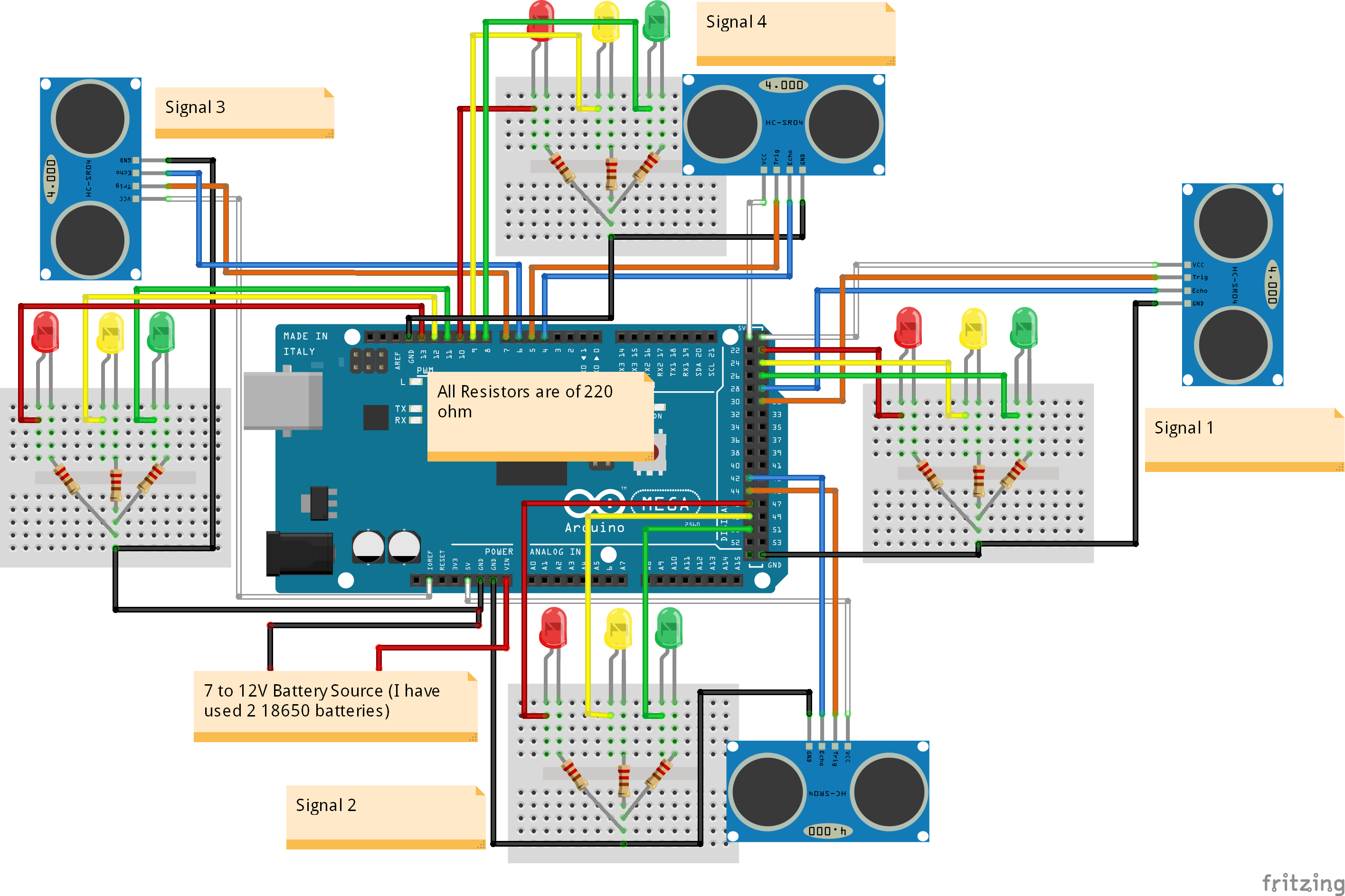
Density Based Traffic Light Controller Using Arduino Arduino Project Hub
A car wiring diagram can look intimidating, but once you understand a few basics you’ll see they’re actually very simple. A car wiring diagram is a map. To read it, identify the circuit in question and starting at its power source, follow it to the ground. Use the legend to …

Traffic Light Multisim Help National Instruments
Traffic Signal Stop Light Wiring With Arduino Controller 7. Simple Four Way Traffic Light Circuit. 4 Way Traffic Lights Diagram Electronic Schematics Traffic. Traffic Lights For Model Cars Or Model Railways Circuit Schematic. Traffic Light Circuit Diagram Using 555 Timer Ic. T3 Controller. Circuit Diagram Of Traffic Light And Rpi Plc Connections.
Archaic Digital Design
NEMA Traffic Signal Cabinets shall connect to NEMA TS2 Type A2 capable of supporting a complete set of cabinet wiring drawings, intersection diagrams, accommodate twelve load switch sockets, six flash transfer relay. Traffic signal control cabinets represents one of the most important intelligent Click below to read about Econolite's 6-week lead time and cabinet quality signal control cabinets ...

How Traffic Signals Work Science Projects
Traffic Light Wiring Diagram. Traffic Light Wiring Diagram from www.engineersgarage.com. Print the wiring diagram off plus use highlighters to trace the signal. When you make use of your finger or perhaps the actual circuit with your eyes, it is easy to mistrace the circuit. 1 trick that We 2 to printing a similar wiring plan off twice.
Traffic Signal Timing Manual Chapter 4 Office Of Operations
Wiring Diagrams. Control Switch Wiring Diagram (500 Kb) Traffic Indicator Signal Installation Guides. TCIL Series (LED Traffic Controller Indicator) Installation Guide 120-277V (902 KB) TCIL Series (LED Traffic Controller Indicator) Low Volt Installation Guide (822 Mb) Light Source Replacement Instructions (signs before 08/01/17) (826 Kb)

How To Build An Arduino Traffic Light Controller 4 Way Arduino Project Hub
Wiring Diagram Trailer Plugs and Sockets. Narva 7 and 12 pin trailer connectors comply with all relevant ADRs. Flat connectors comply with Australian Standards AS4177.5-2004. Large and small round connectors comply with AS2513-1982 while Heavy duty connectors meet the AS4735-2003 standard as required for vehicles and trailers over 3.5 tonnes.

Circuit Diagram For Density Based Traffic Light Control System Eceprojects
15.1.2 TRAFFIC CONTROL SIGNAL SYSTEMS WIRING REQUIREMENTS . Traffic control signal cable must be stranded copper with a conductor size of number 14 AWG [3 conductor 14 AWG (3/C 14)], rated for 600 volts, and suitable for use at 90°C in wet or dry locations . This cable is used for the luminaries atop the traffic control signal poles, cable from
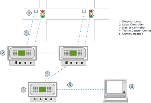
Traffic Signal Systems A Review Of Current Technology In The United States
Traffic Signal Cabinet Wiring Diagram Collection. Variety of traffic signal cabinet wiring diagram. A wiring diagram is a streamlined conventional pictorial representation of an electric circuit. It reveals the elements of the circuit as simplified forms, as well as the power and signal links between the tools. A wiring diagram typically provides info about the family…
Solved What Would Be A Good Way To Explain This Wiring Chegg Com
Below is a wiring diagram for the traffic signal. Hopefully this is pretty clear what gets wired to what. Above is a photo of the Arduino Uno and the relay ...
2
Field Wiring Diagram Interconnect Layouts For Information Only Sheet(s) Utilities 8 Title Sheet Title Sheet -The title sheet is required for all traffic signal plans. It includes information such as the title block, project location, governing specifications, etc. 9 Title Sheet -Plan Preparation Certification Note
2
TRAFFIC SIGNAL DESIGN HANDBOOK. Bureau of Maintenance and Operations . Publication 149 . October 14, 2010 (May, 2013 Update)
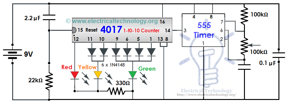
Traffic Light Control Electronic Project Using 4017 555 Timer
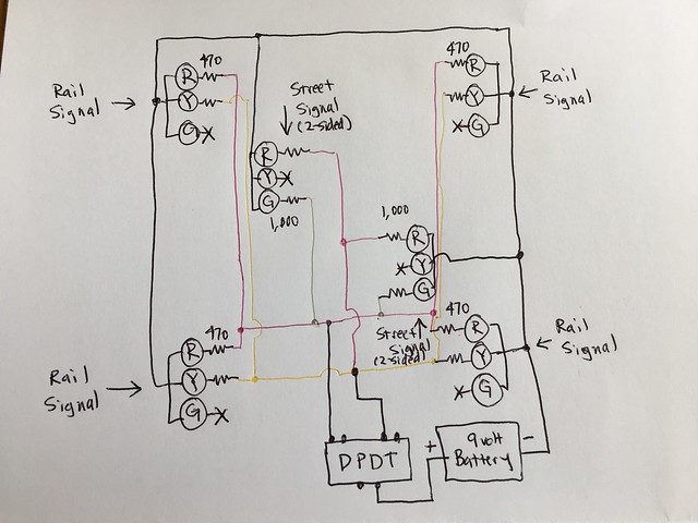
Wiring Walthers Led Traffic Signals With Dpdt Need Some Help Model Railroad Hobbyist Magazine
Traffic Signal Stop Light Wiring With Arduino Controller 7 Steps With Pictures Instructables

Complete Circuit Diagram Of The Designed Microconroller Based Traffic Download Scientific Diagram

Mndot Sample Plan Jerry Kotzenmacher Mndot Ppt Download
Simple Traffic Light Diagram Hd Png Download Kindpng
2
2
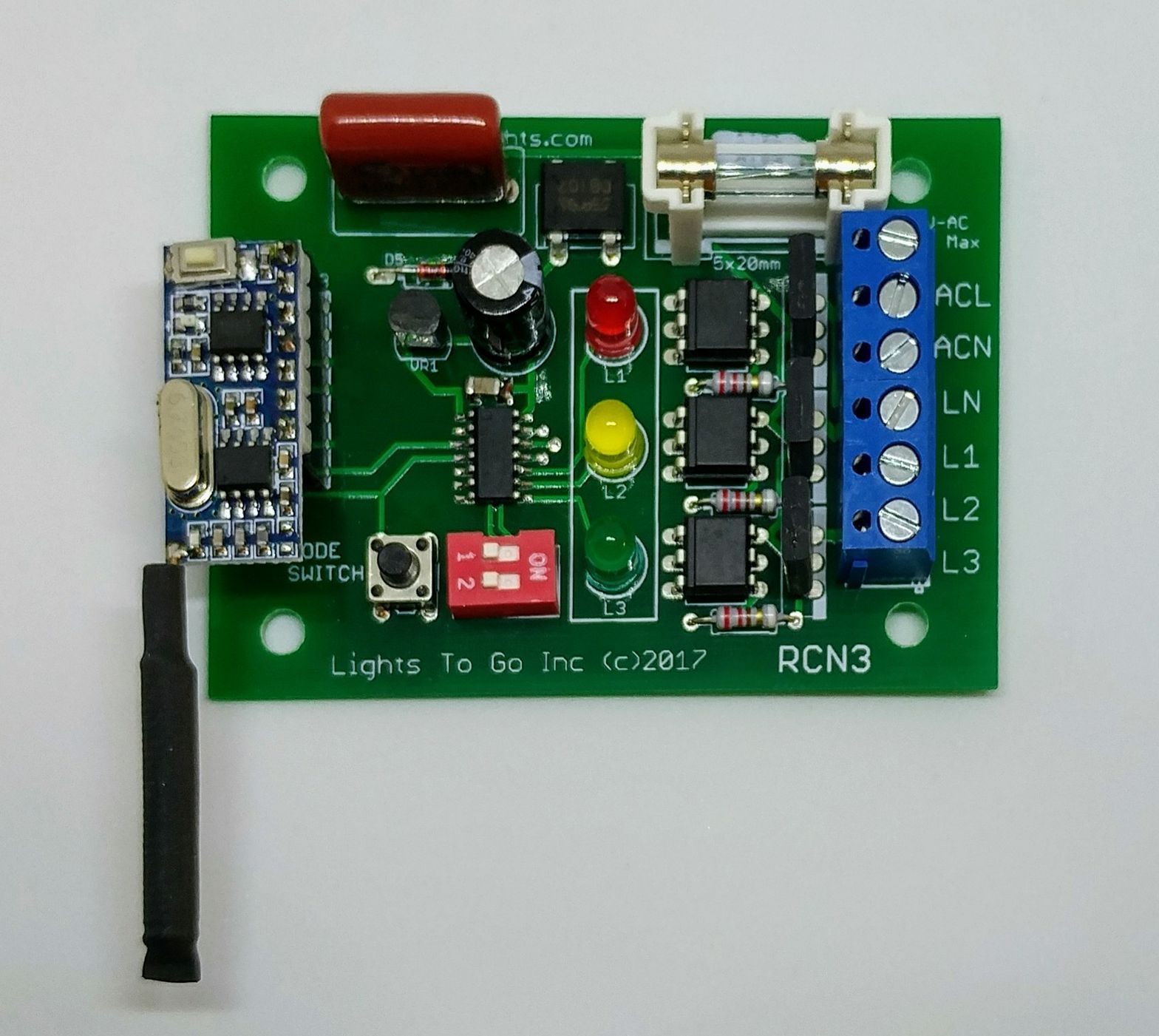
Remote Control Traffic Light Controller

Two Way Traffic Light
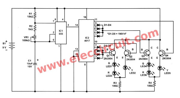
Traffic Light Controller Circuit Using Cd4027 Ne555

Circuit Diagram Of Traffic Light And Rpi Plc Connections Download Scientific Diagram
Pic Traffic Lights

Traffic Lights For Model Cars Or Model Railways Circuit Project Traffic Light Model Trains Circuit Diagram
Comments
Post a Comment