40 water flow diagram
The flow charts are an ideal tool to analyze not only energy but also carbon, water, and other relevant “networks.” Such analyses provide insights that simultaneously enable system optimization, for example, identifying underused resources or the need for better technology, and reveal cross-system couplings, such as water demand for electricity generation. water flow direction salt water osmotic pressure fresh water water moves to higher salt content side semi-permeable membrane osmosis water flow direction fresh water ... desalination — process flow diagrams schematic of swro process employing dweer energy recovery device feed lp feed hp brine hp brine lp permeate flowserve products brine ...
Access 130+ million publications and connect with 20+ million researchers. Join for free and gain visibility by uploading your research.

Water flow diagram
Ford F150 Heater Hose Diagram. ford 4 6 5 4 6 8 heater hose under intake replacement ford 4 6 5 4 6 8 heater hose under intake replacement the easy way 1999 ford expedition 5 4 heater hose 99 ford f150 heater 1997 ford f150 4 6 heater hose diagram imageresizertool 1997 ford f150 4 6 heater hose diagram moreover 6e944 2004 ford explorer 4 0 one vac line along with 2d4cs 2004 ford explorer 4 0l ... Distribution System Distribution ... individual streets. Service connections to branch mains deliver water into residences. Pumping stations are used to increase pressure and to maintain adequate supply flows.... Oil Sands Process Flow Diagram. Edit this example. Water Recycling Process Flow Diagram. Edit this example. Wind Energy Process Flow Diagram. Edit this example. Drinking Water Treatment Process Flow Diagram. Edit this example. Oil Refining - Hydrodesulphurization.
Water flow diagram. The water cycle is an important Biogeochemical Cycle involved in the flow or circulation of water through different levels of the ecosystem. The water cycle is defined as a natural process of constantly recycling the water in the atmosphere. It is also known as the hydrological cycle or the hydrologic cycle. Select your data including the column and row headers, exclude the Sales Flow column. Go to the Charts group on the INSERT tab. Click on the Insert Column Chart icon and choose Stacked Column from the drop-down list. The graph appears in the worksheet, but it hardly looks like a waterfall chart. Water Management Plans for Healthcare Facilities Editable Water System Process Flow Diagrams. The Centers for Disease Control and Prevention (CDC) and the American Society of Heating, Refrigerating, and Air Conditioning Engineers (ASHRAE) recommend that healthcare facilities include a water flow diagram as part of their water management plan. a REVERSE ROTATION pump in a serpentine setup still pumps water in the same diection. the serpentine pump is just designed to do so by spinning the opposite direction of the V-belt pumps. the Gen II LT1/LT4 are the only small blocks that use a REVERSE FLOW pump, which cools the heads first, rather than the block. Currently undergoing resto.
A free customizable process flow diagram template is provided to download and print. Quickly get a head-start when creating your own process flow diagram. November 17, 2020 - Fig. 13.7 Concentration/mass flow rate diagram. (a) Schematic of a water using process for impurity. (b) A water-using process in a concentration/mass flow rate diagram, with the water profile not limited for one impurity. (c) The water profile is limited (one impurity). Im wondering the direction of water flow. By looking at the pump and the fan direction, Im thinking the water goes IN at the intake and pumps out from the waterpump, pushing the water UP through the radiator. If this is correct, Im thinking a thermostate stuck closed may be the problem. Process flow diagrams in minutes! • Map how water flows through your facility’s water systems. • Identify Legionella control locations. • Collaborate and share with your water management program team. • Add diagram to ASHRAE 188 water management plans. • Export report data to fulfill document requirements.
HOT WATER HEATING SYSTEM BASICS AND DIAGRAM. Hot water heating systems (Figure below) transport heat by circulating heated water to a designated area. Heat is released from the water as it flows through the heating unit (coil, terminal). After heat is released, the water returns to the boiler to be reheated and recirculated. water flow diagram architecture landscape - Google Search How a Toilet Works – Toilet Plumbing Diagram. One of these devices—called a ballcock—is connected to the water supply and controls delivery of water to the tank. When the tank’s water rapidly drops down into the bowl (upon a flush), the pressure causes the bowl’s waste water to go down the drain. The drop in water level is sensed by a ... In this diagram you must decide the path the water flows from the valve to the farthest head and calculate that distance in feet. The water flow path is shown in Fig. 2 and is represented by the pipe with the check pattern. Notice the distance of the branch line is NOT included in the distance. This is because the water flowing to the
Santa Maria de Valverde
RO Water Purifier Connection Diagram. Here is an uncomplicated diagram of how the RO system functions. The RO water purifier flow diagram given below identifies the stages, while the arrows suggest the flow of water.
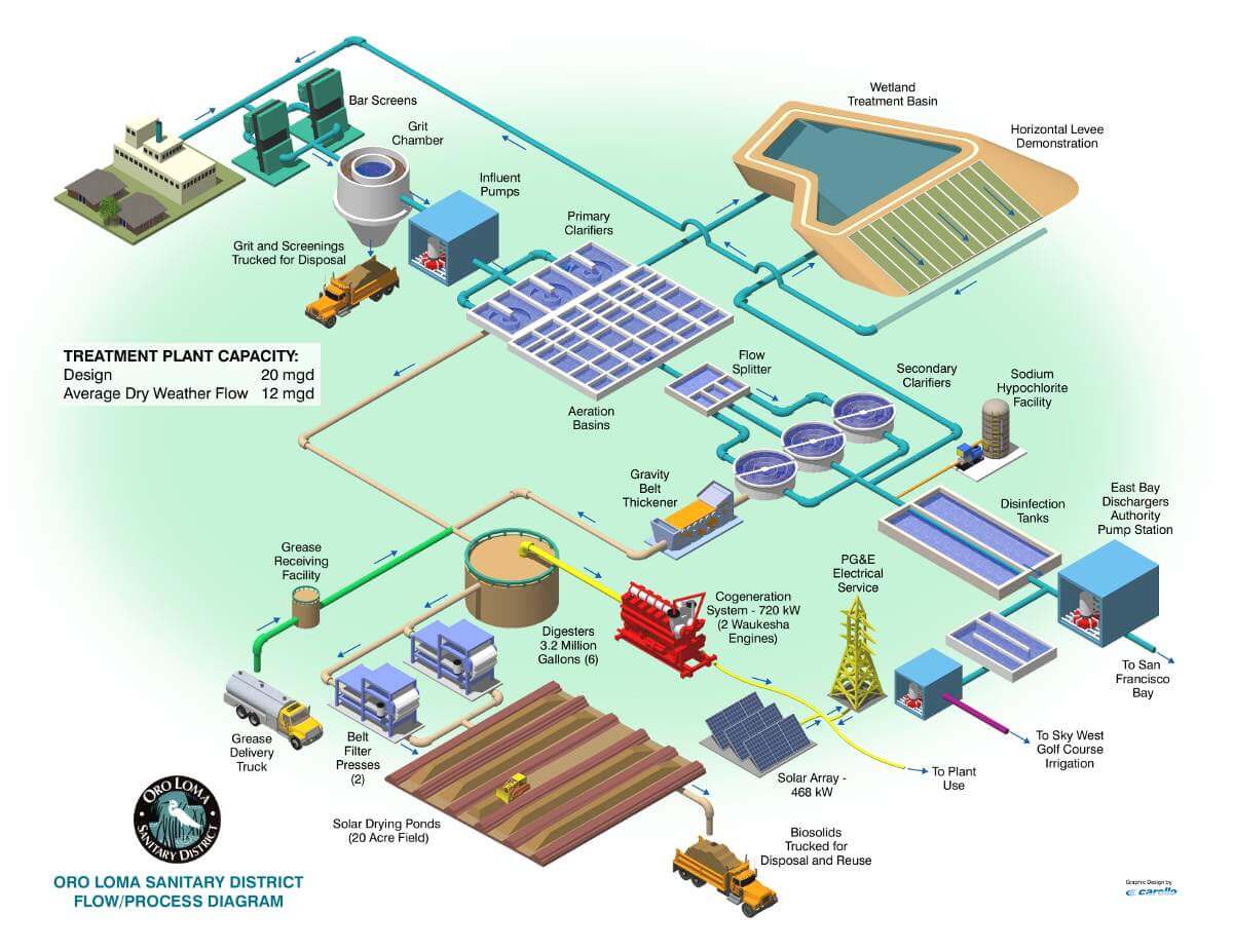
Sewage Treatment - oroloma.org : oroloma.org
Many translated example sentences containing "water flow diagram" – German-English dictionary and search engine for German translations.
Circular Flow Diagram - Water Pollution
Download scientific diagram | SE113 Water Flow Control Schematic Diagram from publication: Performance Evaluation for SE 113 Flow Control System Plant Using ...

where Seattle's drinking water comes from
The Waste Flow Diagram (WFD) tool estimates the amounts of solid waste that leak into nature and oceans by various sources. Through a scenario function, ...
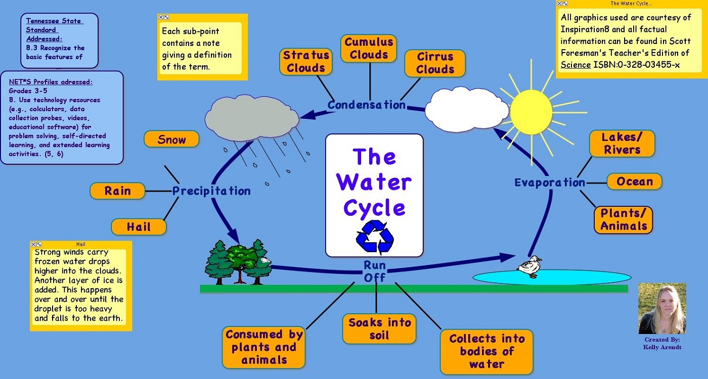
Diagram of Water Cycle | 101 Diagrams
Swimming Pool Plumbing Diagrams 1 Standard Skimmer with 2 Main Drains & 3 Returns. Swimming Pool Main Drains must be installed in accordance with the VIRGINIA GRAEME BAKER POOL AND SPA SAFETY ACT and all applicable ASME/ANSI safety standards. *American National Standards Institute and published by the American Society of Mechanical Engineers.
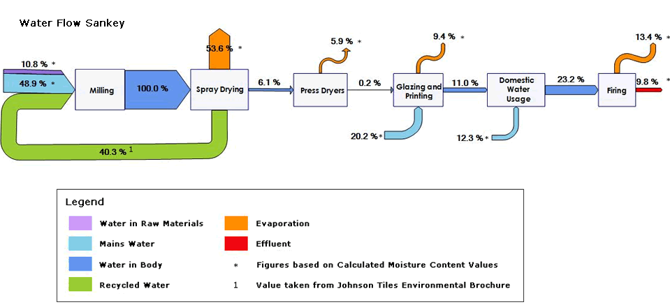
water | Sankey Diagrams
Signals the pump to start when the water system drops to a pre-set low pressure, and to stop when the high-pressure mark is reached. 13. Safety Switch For electric control and distribution to the pump. 14. Pump Saver Adjustable, solid control monitors system load conditions to protect pump motor from dry well flow

IELTS Sample Charts for Writing Task 1
April 8, 2015 - Jan 10, 2014 - This Pin was discovered by Otto Chen. Discover (and save!) your own Pins on Pinterest

IoT Based Water Flow Meter
Figure 3.1. PFD for the pH correction section of a water treatment plant. The lines on this diagram are labeled in such a way as to summarize the mass and energy balance, with flows, temperatures, and compositions of streams.

A process flow diagram and monitoring points of the ...
dataflow water billing [classic] Use Creately's easy online diagram editor to edit this diagram, collaborate with others and export results to multiple image formats. You can edit this template and create your own diagram. Creately diagrams can be exported and added to Word, PPT (powerpoint), Excel, Visio or any other document.

Water flow rate and volume measurement using Arduino in ...
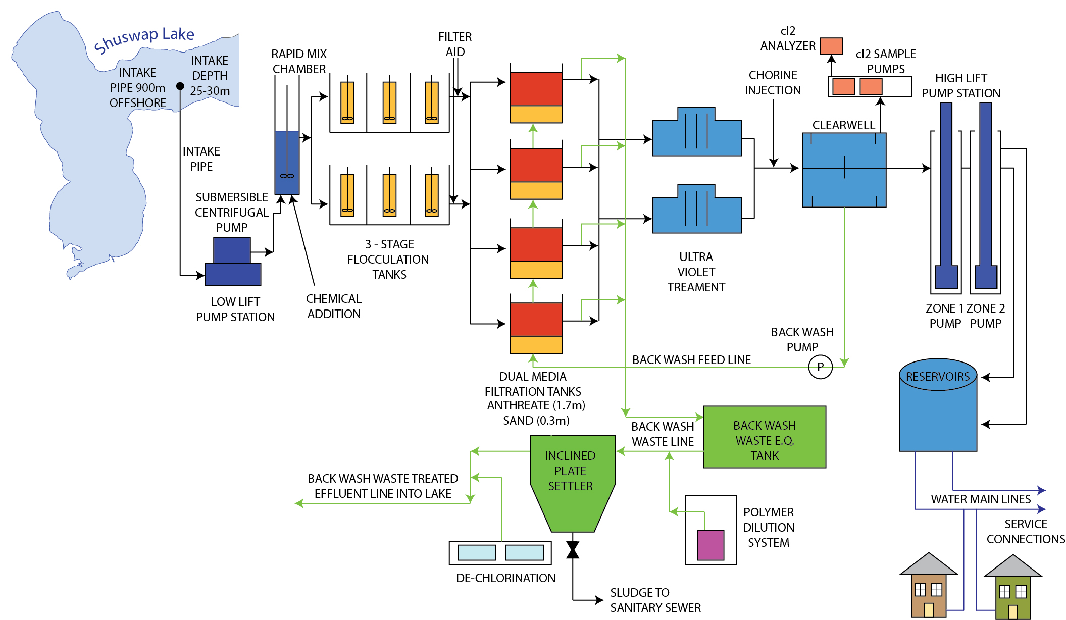
Drinking Water Treatment. Sedimentation. The heavy particles (floc) settle to the bottom and the clear water moves to filtration. Storage. Water is placed in a closed tank or reservoir for disinfection to take place. The water then flows through pipes to homes and businesses in the community. Flocculation. &. Clarification.
Process flow sheets: Purified water production process with flow chart
We use them to give you the best experience. If you continue using our website, we'll assume that you are happy to receive all cookies on this website · United Water New York (UWNY), a provider of water and wastewater services in the US, has proposed a water supply project
Cooling Process Flow Diagram | Free Cooling Process Flow Diagram Templates
ConceptDraw DIAGRAM is a drawings software for creating Nature scenes. Nature solution from ConceptDraw Solution Park expands this software with a new library that contains 17 vector objects and samples illustration files. Draw Diagram Of Water Flow System

Largest Power Plant in Philippines Uses Membrane ...
August 2, 2016 - IPART makes the people of NSW better off through independent decisions and advice · We are the independent pricing regulator for water, public transport, local government, electricity and gas industries, as well as the licence administrator of water, electricity and gas and the scheme ...
Water flow chart - Living Building Chronicle
Viele übersetzte Beispielsätze mit "water flow diagram" – Deutsch-Englisch Wörterbuch und Suchmaschine für Millionen von Deutsch-Übersetzungen.

Determining Your Well Water Flow Rate On Systems With ...
The process flow diagram is an essential part of chemical engineering. It conveys a process and the path of its individual components - therefore, it is essential to learn how to read and create one. The process flow diagram is divided into three sections: process topology, stream information, and equipment information.
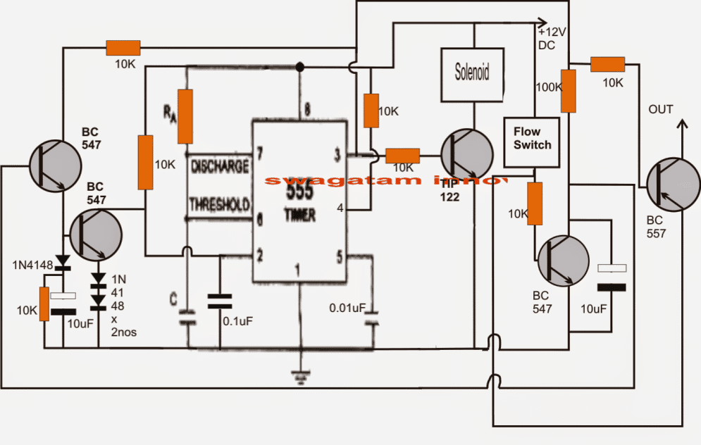
Customized Water Flow Controller with Timer Circuit ...
Home Back to Previous Industries Water & Wastewater Wastewater Treatment Plant Flow Diagram Benefits Water and wastewater applications are one of the largest markets HAWK specializes in due to the wide range of products and technologies we offer.

Conceptual model of water flow in the hydrologic cycle ...
A water system flow diagram provides a schematic (simplified) representation of your facility's water distribution system from the water meter or point of entry (to the facility) to points of use.. Scope. Flow diagrams are examples of concept diagrams used in many types of risk assessment to assist in identifying and understanding hazards (particularly exposures to hazards), hazard sources ...

H6500 RO | Reverse Osmosis | Product Detail
Find water flow chart stock images in HD and millions of other royalty-free stock photos, illustrations and vectors in the Shutterstock collection. Thousands of new, high-quality pictures added every day.

Black Beauty, Equine, Harlow Green, Gateshead, Tyne & Wear, England.
Basic Plumbing Diagram Indicates hot water flowing to the fixtures Indicates cold water flowing to the fixtures *Each fixture requires a trap to prevent sewer/septic gases from entering the home All fixtures drain by gravity to a common point, either to a septic system or a sewer. Vent stacks allow sewer/septic gases to escape and provide

Evolution timescale debunked by field & experimental evidence
Ls3 engine coolant flow diagram. 19354328 ls3 engine control system kit. 19329243 thank you for choosing chevrolet performance as your high performance source. The ls3 should be the same. Rev 16oc14 part no. Mass air flow sensor and engines throttle body. Lsx engine have traditional coolant flow block first then the heads and out.
Download Description Moody Diagram Jpg | Gantt Chart Excel ...
A data flow diagram is a graphical representation of the flow of data through an information system. See Category:Data flow diagrams. Function Block Diagram. A Function Block Diagram (FBD) is a diagram, that describes a function between input variables and output variables. A function is described as a set of elementary blocks.
Process flow diagram of water quench tower and dilution ...
The water jacket is a collection of passages within the block and head. These passages let the coolant circulate around the "hot spots" (valve seats and guides, cylinder walls, combustion chamber, etc.) in order to cool them off. The engine block is actually manufactured in one piece with the water jackets cast into the block and cylinder head.

Miami Science Museum - Water Flow Diagram « Inhabitat ...
The water supply system flow diagram should be checked and signed off by those with appropriate knowledge of the system. Someone should be formally assigned an authority for sign off on the accuracy of the flow diagram. A record (on the diagram or somewhere in the document history) should be kept of the 'when' and 'who' changes and the ...

asimsolutions.blogspot.com: THE FCT URBAN WATER SCHEME ...
Water Corporation acknowledges the Traditional Custodians throughout Western Australia and their continuing connection to the land, water and community. We pay our respects to all members of the Aboriginal communities and their cultures; and to Elders past, present and emerging.

Groundwater - Invisible but Precious - FLOW
Download scientific diagram | Flow diagram of Water distribution system from publication: Modernization in Water Distribution System | In the urban area, the physical infrastructure plays an important role. In water distribution system, the water supplied from the reservoir to the consumer end.
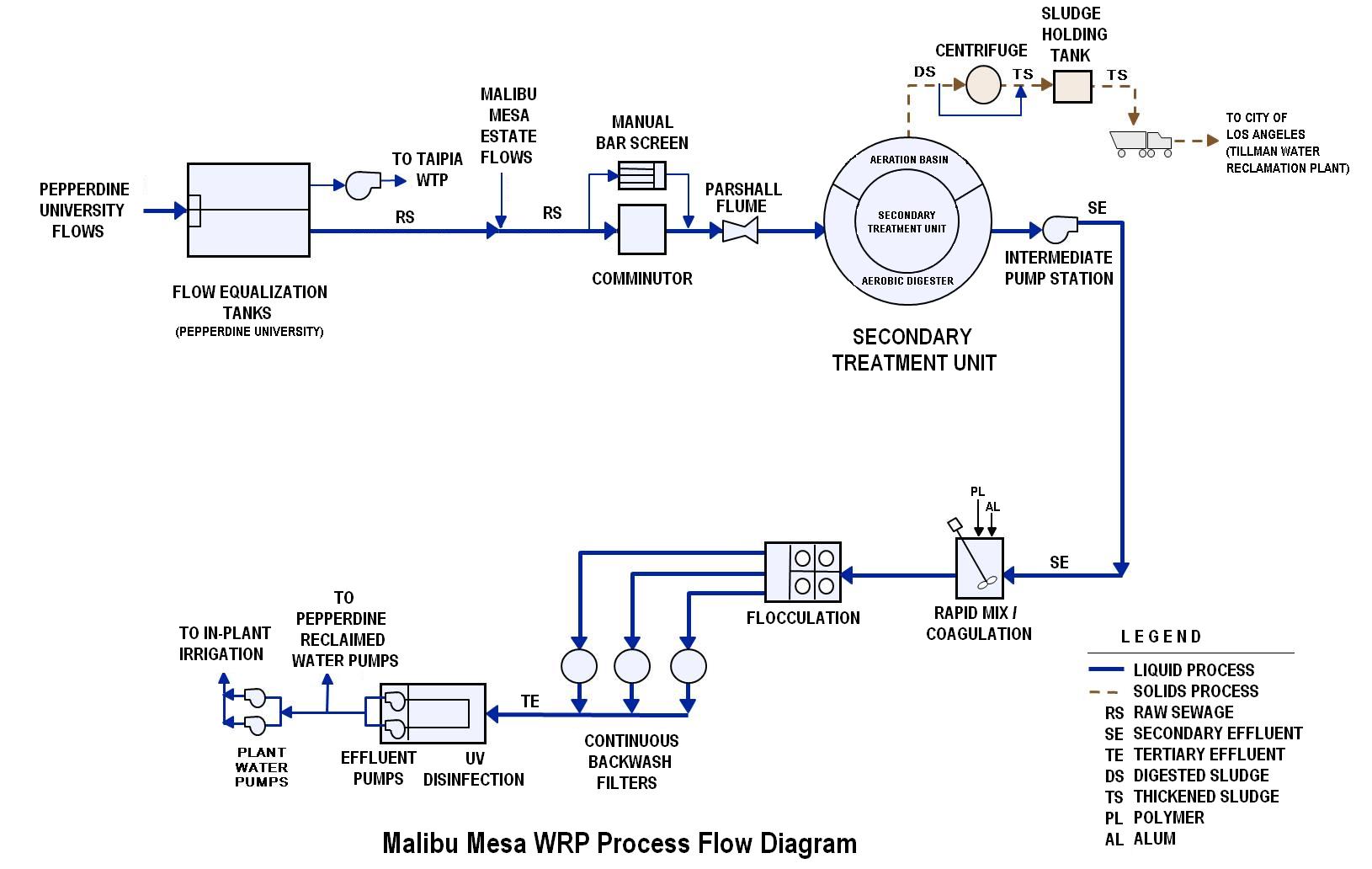
Figure 2-2.Flow Diagram
Module 2: Engineering Fluid Diagrams and Prints Page 1 ENGINEERING FLUIDS DIAGRAMS AND PRINTS To read and understand engineering fluid diagrams and prints, usually referred to as P&IDs, an individual must be familiar with the basic symbols. EO 1.1 IDENTIFY the symbols used on engineering P&IDs for the following types of valves: a. Globe valve g.

Enviromental Balance - Federlegno Environmental Report 2008
Help support my channel by using the link. Ad https://www.amazon.com/shop/omfishing#This is a video of the path the water takes to cool a outboard engine. ...
"Water Environment and Technology, WE&T" article, "A ...
Groundwater Flow and the Water Cycle. Yes, water below your feet is moving all the time, but, no, if you have heard there are rivers flowing below ground, that is not true. Water moves underground downward and sideways, in great quantities, due to gravity and pressure. Eventually it emerges back to the land surface, into rivers, and into the ...

Unesco World Heritage Site, Architecture, Chateau De Chambord, Chambord, Loire-Et-Cher, French Republic.
Access 130+ million publications and connect with 20+ million researchers. Join for free and gain visibility by uploading your research.
Knowledge - 'Flow diagram of water treatment plant' - Viden.io
Oil Sands Process Flow Diagram. Edit this example. Water Recycling Process Flow Diagram. Edit this example. Wind Energy Process Flow Diagram. Edit this example. Drinking Water Treatment Process Flow Diagram. Edit this example. Oil Refining - Hydrodesulphurization.

Electromagnetic flow meters - Design and Development ...
Distribution System Distribution ... individual streets. Service connections to branch mains deliver water into residences. Pumping stations are used to increase pressure and to maintain adequate supply flows....

Flow diagrams of U.S. and Western water use - EcoWest
Ford F150 Heater Hose Diagram. ford 4 6 5 4 6 8 heater hose under intake replacement ford 4 6 5 4 6 8 heater hose under intake replacement the easy way 1999 ford expedition 5 4 heater hose 99 ford f150 heater 1997 ford f150 4 6 heater hose diagram imageresizertool 1997 ford f150 4 6 heater hose diagram moreover 6e944 2004 ford explorer 4 0 one vac line along with 2d4cs 2004 ford explorer 4 0l ...

2011 estimated us energy water flow diagram - Google ...
WQX Data Flow Diagram | STORET/WQX | Water | US EPA

Water Flow Switch - Temco Controls Ltd.

Monochrome, Unesco World Heritage Site, National Trust, Water Landscape, Giant's Causeway, County Antrim, Northern Ireland.

All about Water Treatment, Waste Water Treatment and Power ...

The artistry of the cell spanning 50 years

Chevy 350 Coolant Flow Diagram - Free Wiring Diagram
PurePro® RO103TDS Flow Diagram
Comments
Post a Comment