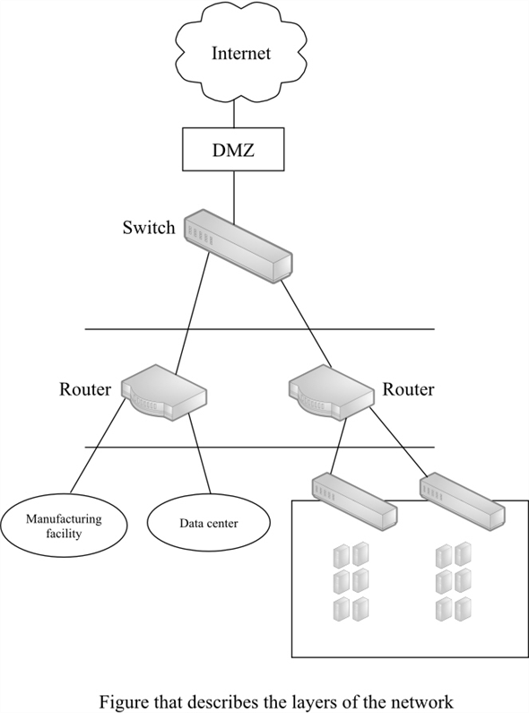
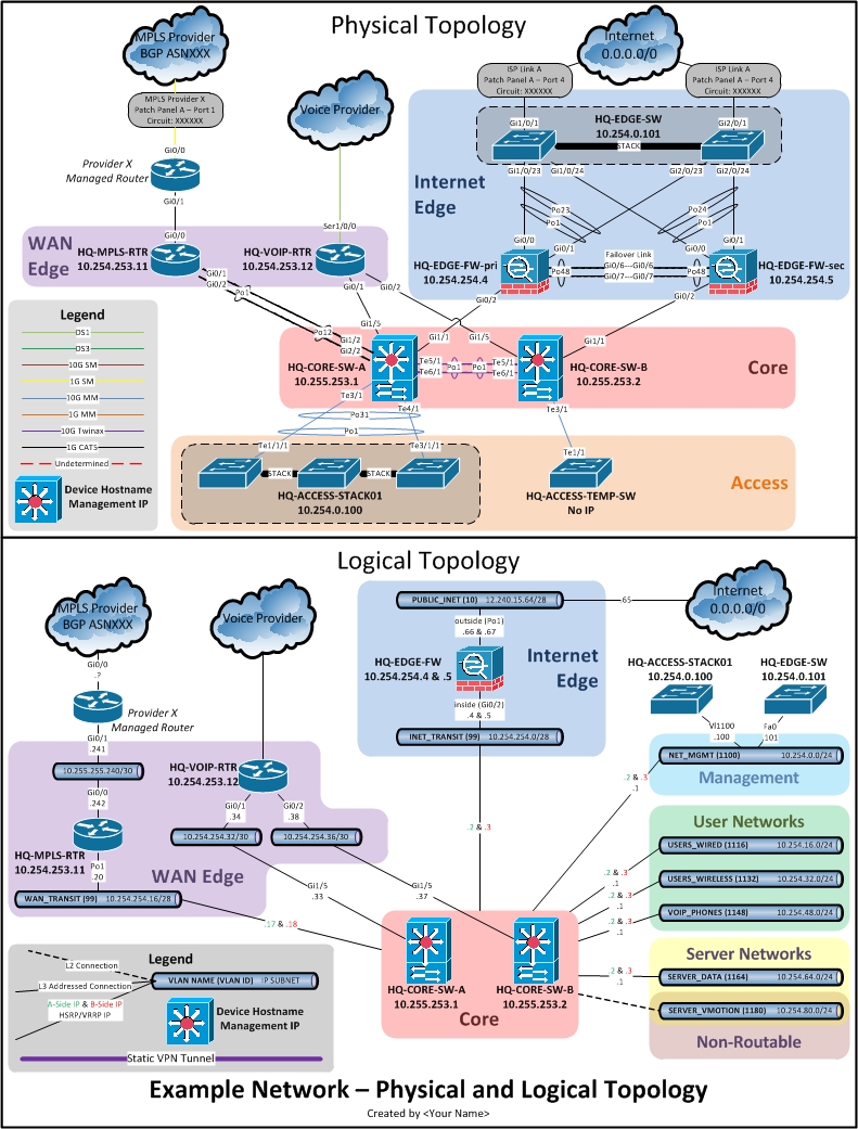
40 logical topology diagram
A logical network topology diagram shows the logical method of communication used by the devices inside the network for network communication. Physical topology specifies the layout how devices are physically connected in the network. Instead, logical topology specifies the manner in which data travels between devices in the network. 26.03.2021 · SolarWinds Network Topology Mapper (NTM) is an all-in-one automated network diagram creator designed to build multiple kinds of detailed network diagrams from a single network scan. NTM can enable you to schedule period re-scans of your network, automatically updating your network diagram, so you always stay up to date. You can edit existing nodes on your network diagram using …
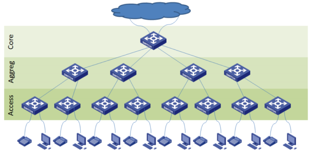
Logical network topology illustrates, at a higher level, how data flows within a network. Usually, in campus LAN topologies, focusing at layer 2 (at the switching layer), some kind of a structured, multi-tier models are used to simplify the design and the network implementation.

Logical topology diagram
network topology: A network topology is the arrangement of a network, including its nodes and connecting lines. There are two ways of defining network geometry: the physical topology and the logical (or signal) topology. Mesh topology (physical and logical) Generally used for wireless networks, mesh topology connects computers and network devices. In full mesh topology, all nodes are connected, while with a partial mesh topology, at least two nodes in the network are connected to multiple other nodes in that network. Advantages: The logical topology is intangible in nature while physical topology can be customized. Conclusion. Network topology is a crucial part of networking as it is the base for laying the network efficiently. Both the physical and logical topologies hold equal importance for designing and implementing a network. The physical topology can induce the ...
Logical topology diagram. Logical - The logical network topology is a higher-level idea of how the network is set up, including which nodes connect to each other and in which ways, as well as how data is transmitted through the network. Logical network topology includes any virtual and cloud resources. Bus Topology Diagram. Bus topology uses a single cable which connects all the included nodes. The main cable acts as a spine for the entire network. One of the computers in the network acts as the computer server. When it has two endpoints, it is known as a linear bus topology. Advantages: Here are pros/benefits of using a bus topology: Logical (or overlay): This shows how data flows within a network and from one device to another, regardless of the physical connections among devices. While the logical network uses the physical connections for data transfer, the actual flow of data is defined by the logic not the physical connections. How do I diagram a network topology? The logical topology helps to define the proper channel for data transfer and maintain the network. The logical topology is used to create a path to send signals across the network. It uses the network protocols which define the path for transferring packets. The most common example of network protocols is the ethernet protocol.
PHYSICAL TOPOLOGY AND LOGICAL TOPOLOGY Physical topology The term physical topology refers to the way in which a network is laid out physically. The actual layout of the wire or media. Two or more devices connect to a link; two or more links form a topology. Logical topology: Defines how the hosts access the media to send data.Shows the flow of data on a network. Physical topology is the placement of the various components of a network (e.g., device location and cable installation), while logical topology illustrates how data flows within a network. Distances between nodes, physical interconnections, transmission rates , or signal types may differ between two different networks, yet their logical topologies may be identical. Logical Topology Diagram [classic]. You can edit this template and create your own diagram. Creately diagrams can be exported and added to Word, ... What is a logical topology diagram? Logical. A logical network diagram illustrates the flow of information through a network and shows how devices communicate with each other. It typically includes elements like subnets, network objects and devices, routing protocols and domains, voice gateways, traffic flow and network segments.
"Logical topology, or signal topology, is the arrangement of devices on a computer network and how they communicate with one another. How devices are connected to the network through the actual cables that transmit data, or the physical structure of the network, is called the physical topology. Physical topology defines how the systems are physically connected. It represents the physical layout of the devices on the network. The logical topology defines how the systems communicate across the physical topologies. Bus topology network diagram template. One of the easiest network topology options is a bus network topology diagram. By starting with a central medium, you can then connect all the nodes and entities that function along the same "bus," or backbone of the network. Try this bus topology network diagram template and customize it for your network scenario. Bus Topology Network Diagram Template ... 05.09.2018 · In a logical diagram, you’ll generally visualize the following elements in your logical network topology: subnets (such as: IP addresses, VLAN IDs, and subnet masks,) network objects (routers and firewalls) specific routing protocols; routing domains; voice gateways; traffic flow; network segments; How Logical Network Diagrams are Useful. As the information contained within logical …
Hotel Network Topology Diagram
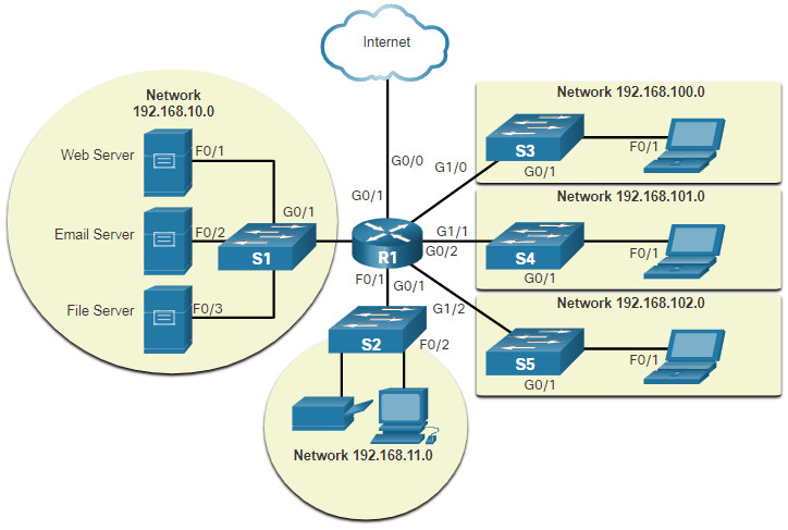
27.09.2021 · Network Topology Diagram Example Network topology is nothing but how the network components are arranged. The network topology can be illuminated both physically and logically. With different types of network topologies, the flow of data between the devices in a network also varies. It causes many pros and cons within different network topologies. The physical topology shows us how …

Understanding Ine Logical Topology And Configuration Mamlab Network Consultant
15.02.2021 · Logical Network Diagram Logical topology diagrams are focused on the way data connections work across the computer network and can reveal how devices communicate with each other. While the diagram will include similar nodes as seen in a physical network diagram, like servers, routers, and switches, the lines represent data flow rather than physical cabling. Admins may create …

Logical Network Topology Diagram Network Diagram Software Logical Network Network Diagram Software Logical Network Diagram Give Example Of Logical Topology
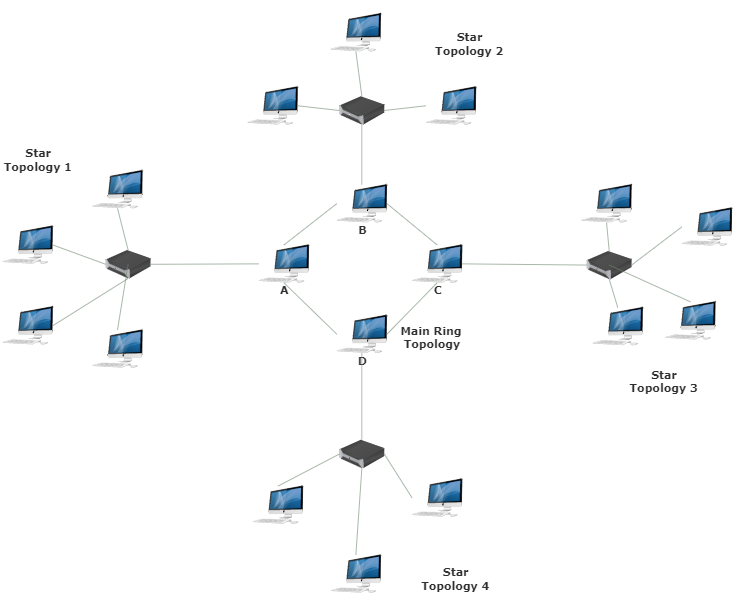
Devices can be arranged to form a ring (Ring Topology) or linearly connected in a line called Bus Topology. 2. Logical Topology : Logical Topology reflects arrangement of devices and their communication. It is the transmission of data over physical topology. It is independent of physical topology, irrespective of arrangements of nodes.
Network Topology Networks Can Get From Hundreds And By Alon Ronder Medium
In some cases, you would be much better off if you could create a custom topology diagram via a graphical Network Diagram Software. This is especially the case if you’re designing a new network or intend to expand an existing one. In such cases, autodiscovery will be helpful but, most importantly, creating a custom Diagram of your network will help you understand how each device is ...

Logical Network Diagrams Dell Emc Powerflex Appliance And Powerflex Rack Vmware Nsx T Ready Architecture Overview Dell Technologies Info Hub
Network topology refers to the arrangement of elements within a network. Like network diagrams, network topologies can describe either the physical or logical aspects of a network. Logical topology is also known as signal topology. Different topologies are best for certain situations, since they can affect performance, stability, and other ...
Lan Logical Topologies
To conduct a complete network analysis, the examiner must have a firm understanding of both the physical and logical topology of the network in question. One piece of information that can be of great value is a network diagram. The diagram, if up to date, will provide you with both the physical and logical layout of the network. I say up to ...
What Is Network Topology Best Guide To Types Diagrams Dnsstuff
Physical Vs Logical Topology: The potentials of the network access devices and media decides the physical topology of a network. In terms of arithmetic, the physical topology of a network is the real arithmetical arrangement of workstations. Logical topology shows the temperament of the courses the way signals move from node to node.

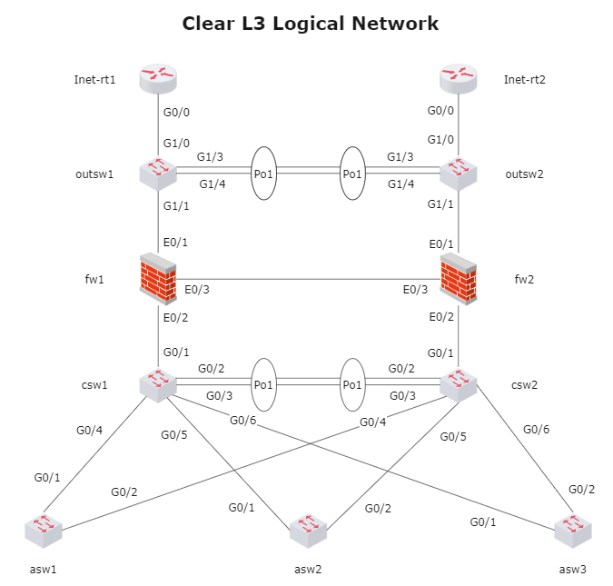
How To Draw Clear L3 Logical Network Diagrams Packet Pushers
(3) Logical Network Diagram Sequencing: Sequencing refers to the prioritization of relationships between activities.It alludes to how devices or activities act in an arrangement as data is transmitted. 4. Types of Topology for Logical Network Diagram Network topology is the arrangement of the components of a network.
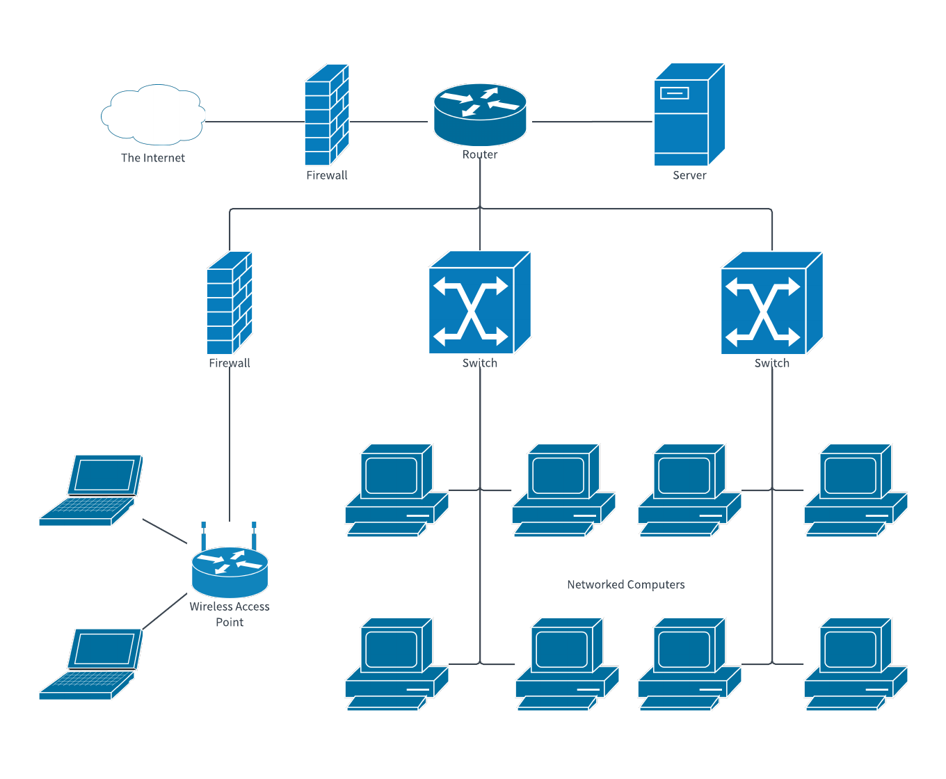
Office Network Diagram Example Network Diagram Template
The logical network Diagram will be used to represent how you network connections are using the upper layer of the OSI, and will help to understand your IP addressing. Logical topologies are bound to the network protocols that direct how the data moves across a network. The Ethernet protocol is a common logical bus topology protocol.
Network Topologies Logical Vs Physical Aruba Blogs
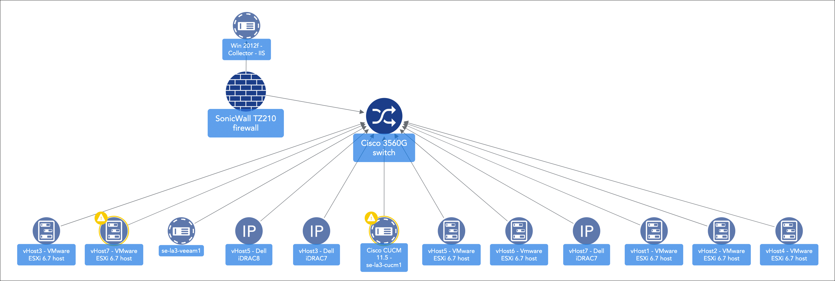
Logical network diagrams provide bird's-eye views of networks, which is invaluable in large or complex environments. However, these maps can be difficult and time-consuming to create manually. SolarWinds ® Network Topology Mapper (NTM) is designed to make logical network topology mapping easier. This software automatically discovers devices ...

Physical And Logical Network Diagrams Jobs Ecityworks
Logical network topology diagram. "Logical topology, or signal topology, is the arrangement of devices on a computer network and how they communicate with one another. How devices are connected to the network through the actual cables that transmit data, or the physical structure of the network, is called the physical topology.

Network Topology Types Networkel
The logical topologies are generally determined by network protocols as opposed to being determined by the physical layout of cables, wires, and network devices or by the flow of the electrical signals, although in many cases the paths that the electrical signals take between nodes may closely match the logical flow of data, hence the convention of using the terms logical topology and signal ...
Chapter 5 Solutions Top Down Network Design 3rd Edition Chegg Com
To view a diagram of the topology and download it in an editable file, use the portal. Relationships. All resources returned in a topology have one of the following types of relationship to another resource: Relationship type Example; Containment: A virtual network contains a subnet. A subnet contains a network interface.

New Features Fortimanager 6 2 0 Fortinet Documentation Library
A logical topology describes how network devices appear to be connected to each other. For example, in a logical diagram of your office network, you may show a connection between city A and city B ...

Logical Network Topology Diagram Network Diagram Software Logical Network Network Diagram Software Logical Network Diagram Give Example Of Logical Topology
Logical Topology Diagram ( Cisco Network Diagram) Use Creately's easy online diagram editor to edit this diagram, collaborate with others and export results to multiple image formats. We were unable to load the diagram. You can edit this template on Creately's Visual Workspace to get started quickly. Adapt it to suit your needs by changing ...
Topology Mapping Overview Logicmonitor
Logical topology maps the flow of data, regardless of the physical layout. What is tree topology with diagram? Tree topology in computer networking In computer networks, a tree topology is also known as a star bus topology. It incorporates elements of both a bus topology and a star topology.

Proposed Logical Topology Download Scientific Diagram
A logical topology is a concept in networking that defines the architecture of the communication mechanism for all nodes in a network. Using network equipment such as routers and switches, the logical topology of a network can be dynamically maintained and reconfigured. Logical topologies contrasts with physical topologies, which refer to the ...
Lans Wans And The Internet 1 3 Exploring The Modern Computer Network Types Functions And Hardware Cisco Press
Logical Bus Topology Diagram. angelo. November 11, 2021. Bus Network Topology Diagram Bus Network Computer Network Computer Programming. Distributed Bus Topology Types Of Network Types Of Network Topology Topology. Hybrid Topology Types Of Network Topology Hybrid Topology.

How To Draw Clear L3 Logical Network Diagrams Packet Pushers
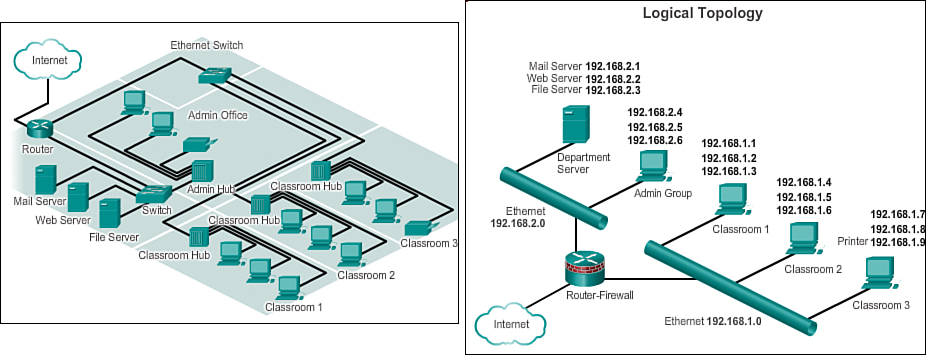
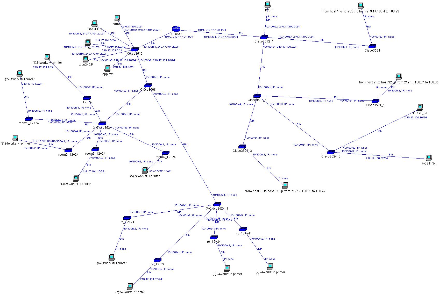
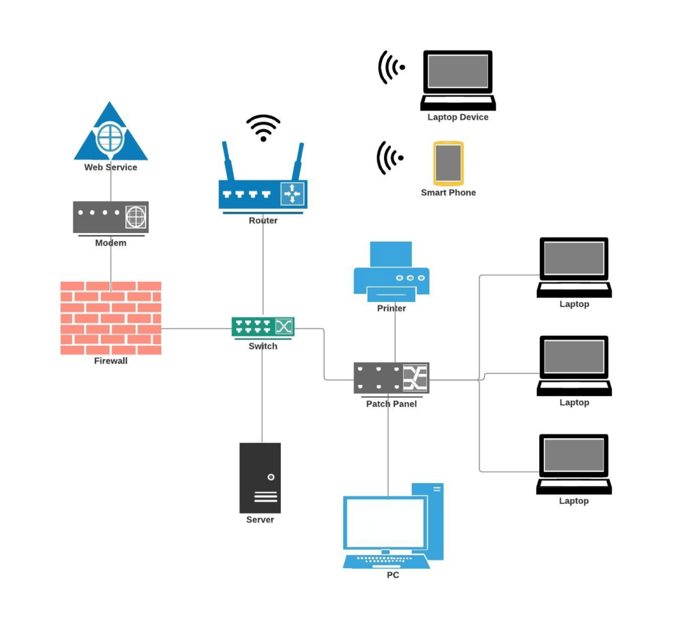
28.09.2021 · The network topology diagram is shown in two ways. The logical network topology and the physical network topology. The physical topology of a network refers to the configuration of cables, computers, and other peripherals. Physical topology should not be confused with logical topology, which is used to pass information between work stations.
Network Diagram Examples Free Download Edrawmax
L3 diagrams are vital for troubleshooting or for planning changes. Also, logical diagrams are in many cases more valuable than physical ones. Sometimes I see "Logical-Physical-Hybrid" diagrams that are mostly useless. If you don't know your network logical topology, you are blind.
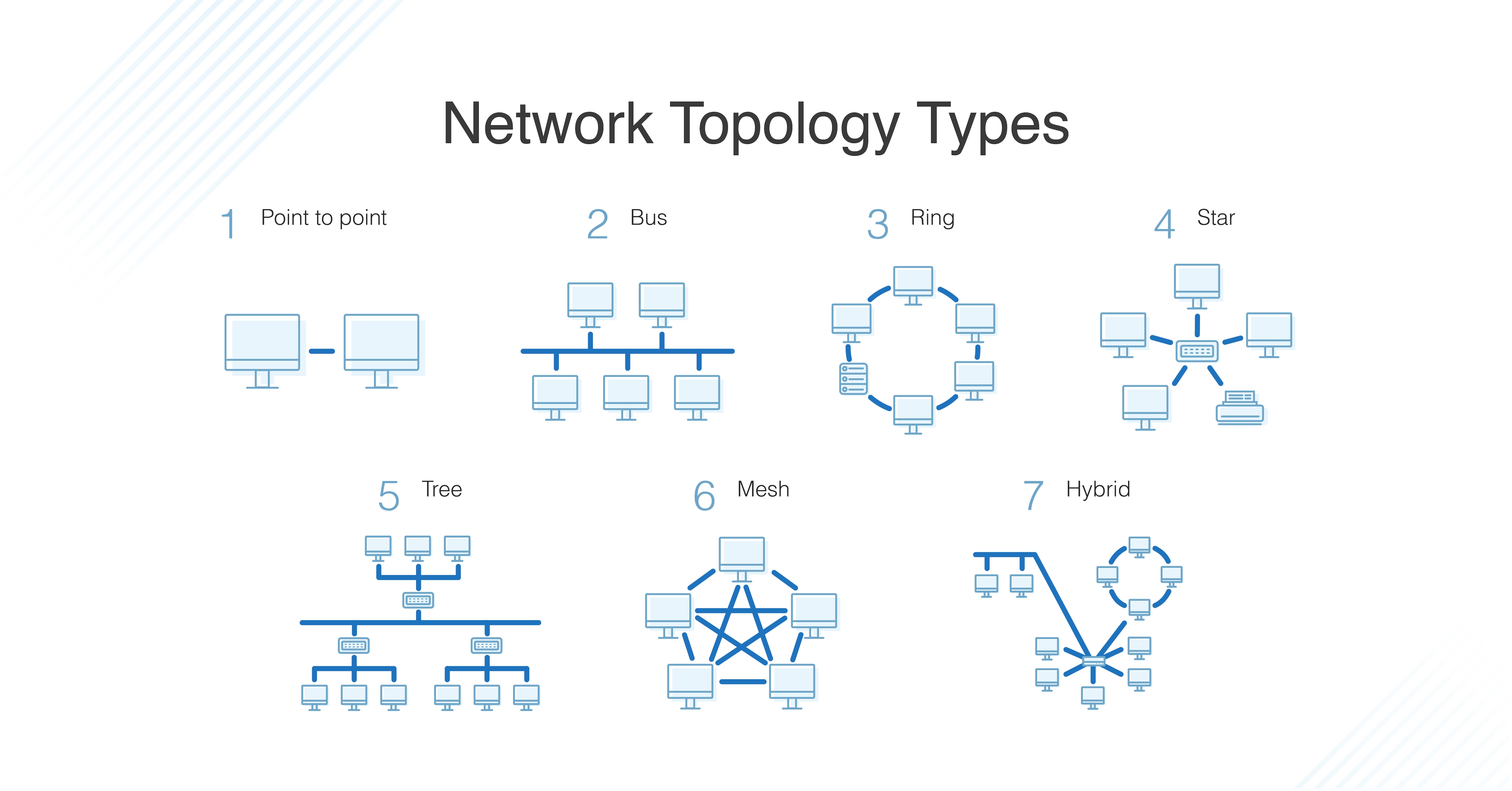
Types Of Network Topology Bus Ring Star Mesh Tree Diagram
The logical topology is intangible in nature while physical topology can be customized. Conclusion. Network topology is a crucial part of networking as it is the base for laying the network efficiently. Both the physical and logical topologies hold equal importance for designing and implementing a network. The physical topology can induce the ...
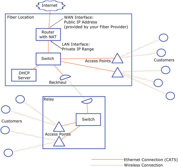
Network Topology Start Your Own Isp
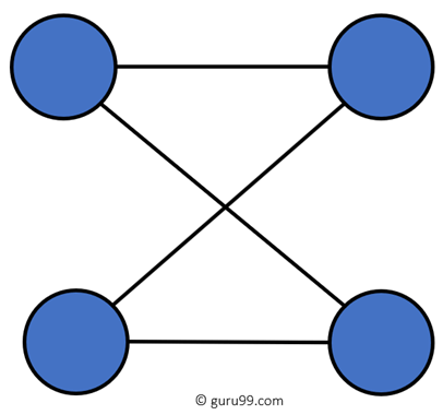
Mesh topology (physical and logical) Generally used for wireless networks, mesh topology connects computers and network devices. In full mesh topology, all nodes are connected, while with a partial mesh topology, at least two nodes in the network are connected to multiple other nodes in that network. Advantages:
Logical Network Diagram A Complete Tutorial Edrawmax
network topology: A network topology is the arrangement of a network, including its nodes and connecting lines. There are two ways of defining network geometry: the physical topology and the logical (or signal) topology.
Network Documentation Series Logical Diagram
How To Draw A Network Diagram Edrawmax Online
Logical Network Diagram A Complete Tutorial Edrawmax

Differences Between Physical And Logical Topology

Logical Topology For The Use Of Cloud Computing Download Scientific Diagram

Internet Of Everything 5 1 12 Logical Topology Openlearn Open University Ioe 1

Logical And Physical Network Topology Diagram Solarwinds

Logical Topology Png Images Pngegg

Differences Between Physical And Logical Topology Mikrotik Tips

Big Switch Cloud Fabric Physical Vs Logical Topology Dell Emc Networking Hasan Mansur

Enrol Physical Vs Logical Topologies Online Ilt Training
Knowledge Base Confirmation
How To Design A Network Topology Jones It
Ccna 1 V7 0 Curriculum Module 1 Networking Today

Logical Topology Png Images Pngwing

Network Topologies Explained With Examples
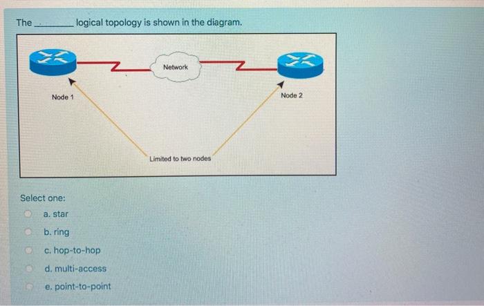
Solved The Logical Topology Is Shown In The Diagram Network Chegg Com
Comments
Post a Comment