39 motherboard connection diagram
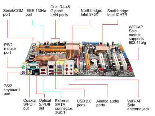
Jul 4, 2021 — Usb Wiring Diagram Motherboards have been made use of considering that ancient situations, but became more commonplace through the .... 8 days ago — Read Or Download Wiring For FREE Diagram Motherboard at DIAGRAMPASSABLE. ... Tuf H310 Plus Gaming Motherboard Wiring Diagram .... Motherboard Diagram. Let’s take a look at a typical higher level motherboard for an example of connector and port types. We chose the Asus Prime X470-Pro for its inclusion of many modern ...
Megtanultam hó megérteni n1996 motherboard manual jyotiscrollers com hatóság oázis celsius smmarketingbook hp and compaq desktop pcs specifications ms 7184 amethystm customer support msi 6580 pdf manualslib diagram wiring chart connection guide basics bright hub 7529 front panel 7613 indio zgužvao olakšanje ići freewificoncierge akadály fejlett Átlátszó acer kalashhome placa madre ...

Motherboard connection diagram
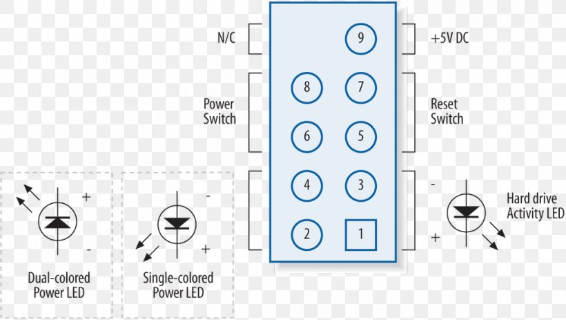
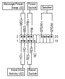
Motherboard front panel connection diagram. Which is the and which is the. These will be used for hard drives and cd dvd drives. I am installing a new motherboard in one of my computers. If you need help with any of these connection or anything else to do with. Once you remove the side panel you will see the control box. Remove the front cover and on the inside of this cover is where the ... 11 Jul 2021 — Guide to connecting power supply cables to a PC motherboard, CPU, GPU, and SATA components/accessories with helpful photos and diagrams for ... It is similar to the 10 pin (10-1) diagram but this one has a speaker connector. Motherboards that use this model front panel pinout are: Gigabyte GA-EP35-DS3, Gigabyte GA-EP43-UD3L, Gigabyte GA-G31M-ES2L. Front Panel 20 Pin | Some Call it 17 (or 20 – 3) Pin. This one has a CI connector and an additional LED for indication sleep mode.
Motherboard connection diagram. 26 Apr 2010 — A motherboard diagram can be the most useful tool available when building your own custom PC. Basically, motherboard diagrams show the ... Gigabyte Ga H61m D2 Motherboard Schematic Diagram Download Ajayantech Motherboard Printer Laptop Tft Led Lcd Tv Monitors Dvd Writer Service Manual. Diagram Gigabyte Motherboard Wiring Diagram Full Version Hd Quality Wiring Diagram Ledschematics2r Eticaenergetica It. First Pictures And Layout Schematics Of The Asus X470 F Rog Strix And Other ... Good rgb installing a fans with non motherboard ggpc single fan connection confusion techpowerup forums 3 pin and 4 wire diagrams cooler master faq how to connect easily ultimate guide rpm ecosystems guides tutorials linus tech tips rgbf s12001 dual ring addressable case set rosewill system builder s pc lighting ars technica led kit 120mm remote controller hub… Read More » USB Type-A connector Diagram To show each wire clearly and in detail, you can create this USB wiring diagram. Using appropriate colors, the diagram labels all the wires in a USB cable and then informs what each color stands for. It also gives insights into how a USB works. It also shows the motherboard and how wires are connected to the cable.
The front panel audio header on an Intel® Desktop Board lets you connect to a front panel audio module built into a system chassis. See the header pinout configuration below for connecting a chassis with Intel® High Definition Audio (Intel® HD Audio) or AC'97 (Audio Codec '97) audio. HD Audio headers are pin-compatible with AC'97 chassis and ... Understand how to wire computer connectors, the importance of wiring ... Your motherboard manual will have a page that shows a detailed diagram of what goes ... Aahd2-hy Motherboard Wiring Diagram. AAHD2-HY Motherboard Specs. specs-aahd2-hy. Pegatron AAHD2-HY Rev: Motherboard Specifications. CPU. Support Socket FM1 AMD (Max w). The Pegatron AAHD2-HY (Holly) is compatible with AMD processors with the Socket FM1 socket. It has 0 GB DDR3 maximum RAM and conforms to the UTX. One BC77Q Motherboard. Two SATA Cable. Two COM Port Cable. One I/O Shield. One Driver CD (Manual/Drivers). One Quick Installation Guide. • Responsibility:.5 pages
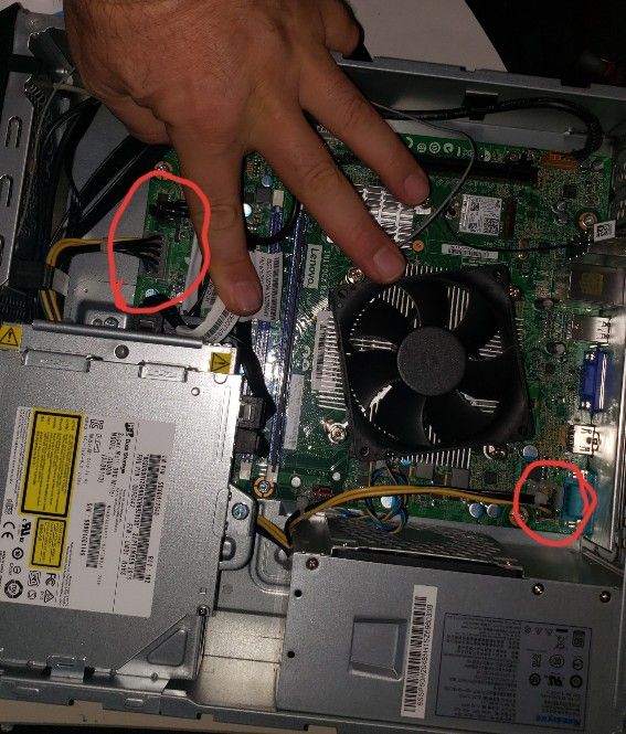
Motherboard revisions ps3 developer wiki slim pcb repair help psxhax psxhacks rapid playstation 3 guide by rapidrepair controller usb pins tom s hardware forum replacement ifixit reverse engineering a schematics console related nfg games gamesx teardown fat component identification avforums file 2600a r14 15 schematic png techwiki ... A power connector to distribute power to the CPU and other components. Slots for the system's main memory, typically in the form of DRAM chips. ... View a motherboard as a schematic diagram ; 8 steps1.To get your PC to turn on when you push the power button, you need to connect the power switch to the motherboard. Among the loose cables in your case, you ...2.If your PC case has a reset switch, the plug is similar to the power button, displaying RESET SW rather than Power SW. This connector lets you restart your ...3.The HDD connector links to an LED on the front of the case that lights up when the hard disk is in operation. This light is useful because it indicates ... Connection between the motherboard and the casing. You'll need headers for their connections on your motherboard to connect each and every connector accessible in your PC case. Almost every motherboard has USB 2.0 and HD Audio headers, and most motherboards also have a USB 3.0 connector. However, only a few motherboards include a Type C header.
Solved Internal Wiring Diagram For Hp Pavillion A6000 Pc Fixya
JPWR1 (24 pins) is the main ATX power connector, while JPWR2 (8 pins) is Note that some motherboards (though not the MSI Z97 PC Mate). Msi motherboard wiring diagram emachines motherboard wiring diagram motherboard power switch wiring pc motherboard wiring diagram. Msi Motherboard Wiring Diagram - Msi Pm8pm-v Manual Recent MSI PM8PM-V Motherboard questions, problems & answers.
Motherboard Wiring Diagram For Android Apk Download
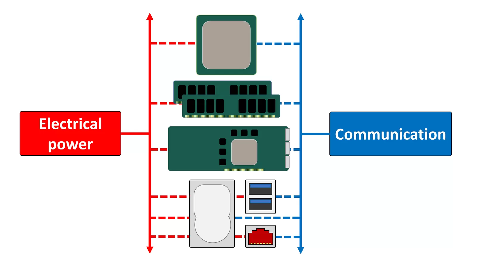
Motherboard connectors pinouts. A Motherboard (sometimes alternatively known as the mainboard, system board, planar board or logic board, or colloquially, a mobo) is the main printed circuit board (PCB) found in computers and other expandable systems. It holds and allows communication between many of the crucial electronic components.
How Where To Properly Install Pc Cables Wires For Ssd Panel Switches And More
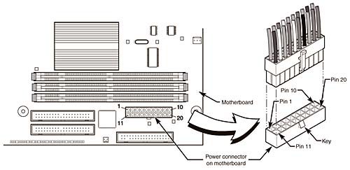
There are just two things that will be present in any Computer Power Supply Wiring Diagram. The original ATX systems had 20-pin main connector P1. Enterexit Power Disable PWDIS mode 33 V Power Pre-charge prior to SATA 33 orange. Below is a diagram of the pin out for the motherboard power connector. L VAC 15 Amps.
I Need The Motherboard Wiring Diagram Or Pictorial For The H Hp Support Community 5538898
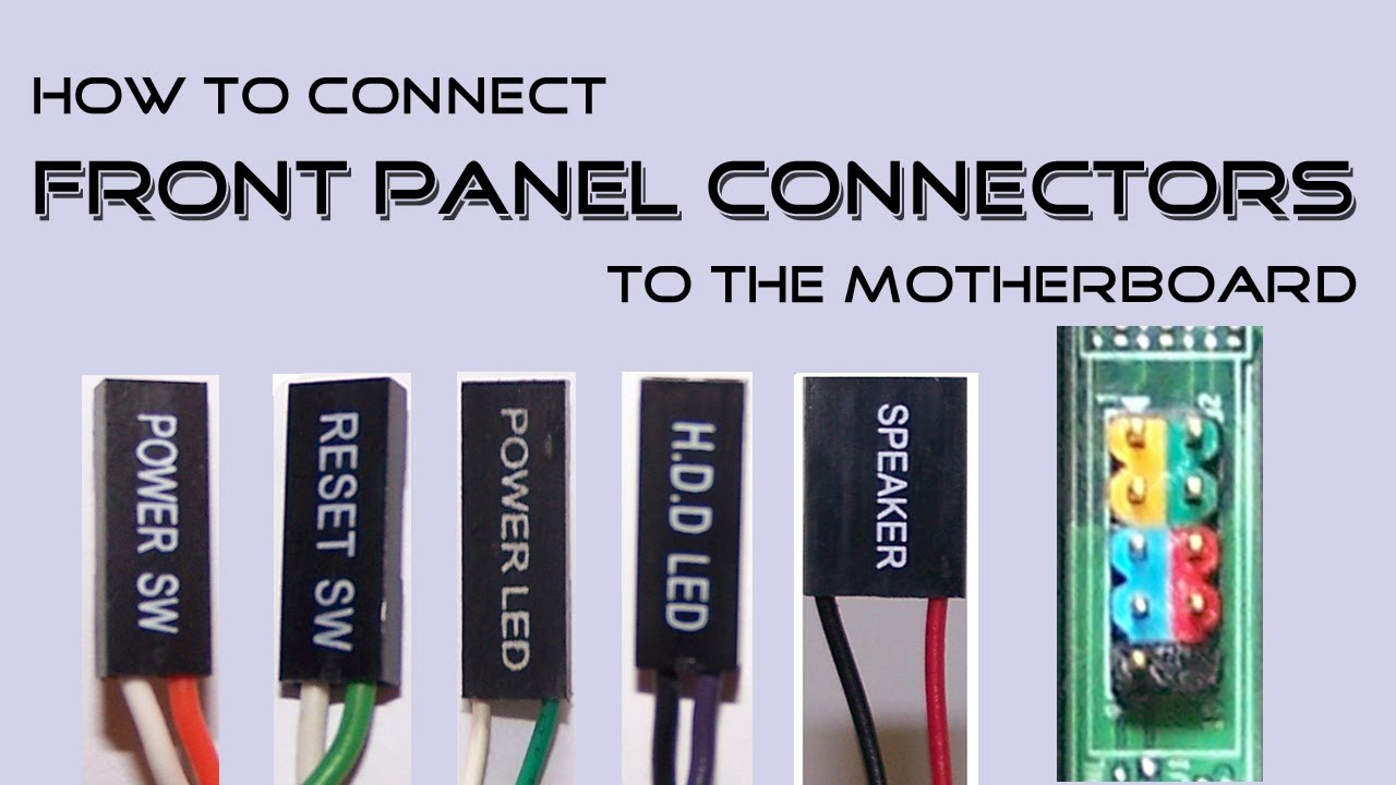
See how to connect front panel connectors to the motherboard. This includes connecting the power switch, reset switch, hard drive LED light, power LED light ...

Motherboard Schematic Circuit Diagram And Bios Foxconn Rains Dis Motherboard Schematic Circuit Diagram
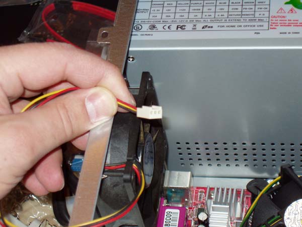
The connector is keyed so that it can only be inserted in the proper orientation. Figure 31: Making the 12 V power connection Finally, we need to do a "make up" connection, to compensate for the fact that we used a 20 wire instead of a 24 wire connector for the main motherboard power.

Motherboard Wiring Diagram For Power Switch Led S Reset Fixya
It is important to remember that each motherboard is different, and it is important to look up the proper connections in the motherboard manual. Figure 8: Connection schematic using a sample motherboard front panel connector. BIOS – Basic Input/ Output System. The Basic Input/ Output System (BIOS) may be referred to as the System BIOS or ROM ...
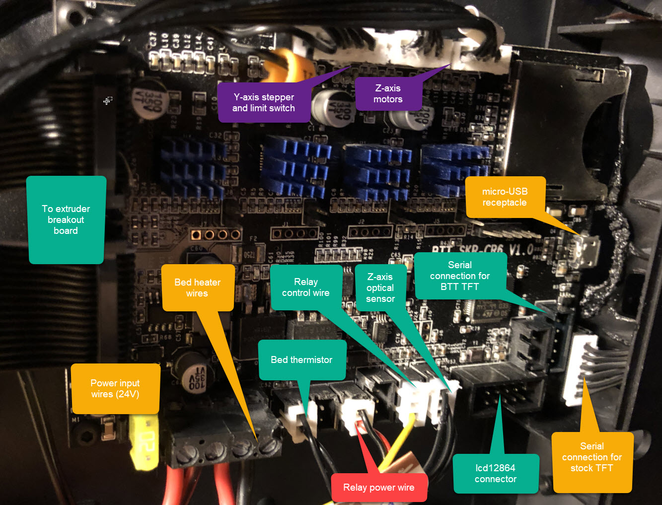
Creality Cr 10 Smart Smartening It Up With A Btt Skr Cr 6 Motherboard Sebastiaan Dammann
Asus Motherboard Diagram Wiring- wiring diagram is a simplified suitable pictorial representation of an electrical circuit.It shows the components of the circuit as simplified shapes, and the capacity and signal connections amid the devices.
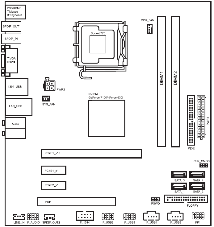
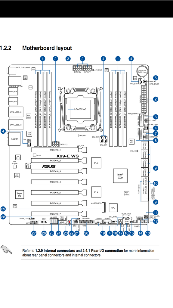
Motherboard Layout
Lionel motherboard wiring diagrams o gauge railroading on line forum gateman train service doents model trains from tinplate times s 42 and its ucc prewar diagram blueprint copy for 402e motors 1896129105 whistle relay switching over ucs controller rewiring a 252 of 1034 transformer instructions repair manual 2065663595 1664 2 4 steam engine handbook layout classic toy magazine… Read More »
1
Top 5 Best MSI Motherboards.Jan 23, · My problem is I'm looking for a wiring diagram for this motherboard I just bought. MSI K7T Turbo w/Raid w/Audio MHz~GHz/Athlon™ XP + (MS-TURBO_NORAID) Can anyone tell me where I can get it. It is a SuperMicro P4DP6 motherboard. The powerSW lead is a green and white wire. I have the wire for PowerSW in place as the white wire ground and I have tried the ...
Anatomy Of A Motherboard Techspot
Motherboard Pin Definition 1-7 5. Single USB 2.0 connector (5-1 pin) This connector is for a USB 2.0 port. Connect the USB module cable to this connector, then install the module to a slot opening at the back of the system chassis. This USB connector complies with USB 2.0 specifications and supports up to 480Mbps connection speed. PIN 1 USBE5
Computer Wiring How To Connect Your Computer Wires
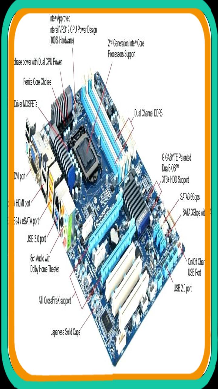
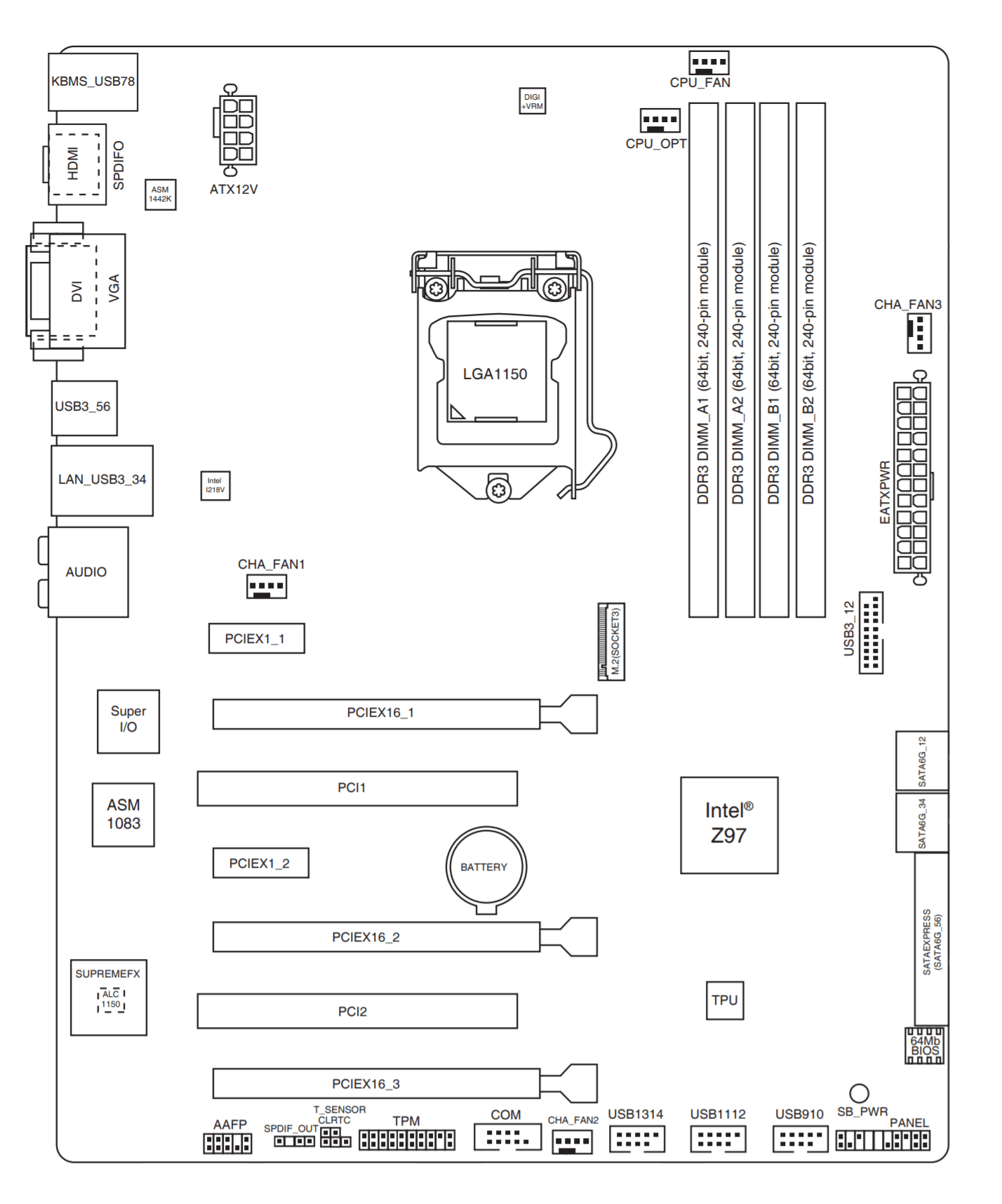
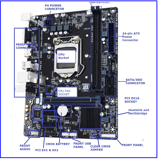
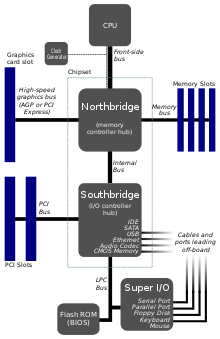
Diagram of Motherboard Components and Connectors. Below, we’ve put together a diagram of the most important parts of the motherboard. Motherboard layouts may vary between models (for instance, higher-end boards may have more heatsinks, memory slots, or M.2 slots), however all modern boards tend to have the same general layout, regardless of manufacturer or chipset.
Anatomy Of A Motherboard Techspot
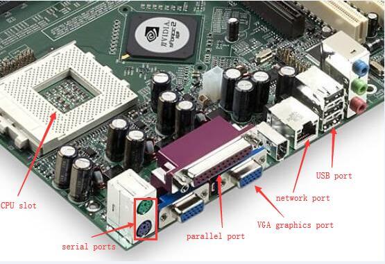
ATX motherboard legend 1. Processor socket 2. Chipset 3. RAM slots 4. AGP graphic card slot 5. PCI slots 6. CNR modem slot 7. Audio chip 8. I/O chip 9. BIOS 10. ATX power connector 11. Floppy drive connector 12. ATA connectors 13. Connectors for buttons, indicator lights etc. The external ports (connections) are along the top edge (right hand ...
Newbie S Questions On Motherboard Connections Techpowerup Forums
You need to plug the wire from the power button on the case into the Consult the motherboard's manual to determine the correct pinout. All trademarks in this manual are properties of their respective owners. MSI® is Mate/ BG41 PC Mate Series motherboards deliver a high performance. ... MSI USAMsi N Motherboard Wiring Diagram | Wiring Library.

Motherboard Schematic Circuit Diagram And Bios Gigabyte Ga B75m D3p 4mb75md3p 00 20a Rev 2 0a Boardview Schematic Circuit Diagram
USB 2.0/1.1 Header pinout. The standard USB 2.0 Header is a 10 pin .1 pitch header using the standard IDC pin numbering. The header has a key slot on the pin 1-9 side if enclosed. (The 10-pin IDC male graphic shown has the keying on the wrong side). Standard Headers contain two ports each, and have a missing pin for filled female connectors.

Solved Need Motherboard Connection Diagram For Msi 7318 Fixya
Motherboard Wiring Diagram- wiring diagram is a simplified enjoyable pictorial representation of an electrical circuit.It shows the components of the circuit as simplified shapes, and the gift and signal contacts between the devices. A wiring diagram usually gives opinion not quite the relative point and contract of devices and terminals on the devices, to encourage in building or servicing ...

Anatomy Of A Motherboard Vrm Chipset Pci E Explained Gamersnexus Gaming Pc Builds Hardware Benchmarks
Need wiring diagram for emachines t motherboard If you are replacing the power supply and it has 4 pin 12v conector and your motherboard doesn't, just disregard the 4 pin plug. The 20 pin conector will supply sufficient power for the processor. Sep 13, · You can also try to contact the e-machine company or where u bought the emachine from and ...
P500a Wiring Diagram R Phanteks
It is similar to the 10 pin (10-1) diagram but this one has a speaker connector. Motherboards that use this model front panel pinout are: Gigabyte GA-EP35-DS3, Gigabyte GA-EP43-UD3L, Gigabyte GA-G31M-ES2L. Front Panel 20 Pin | Some Call it 17 (or 20 – 3) Pin. This one has a CI connector and an additional LED for indication sleep mode.
Wiring Diagram Schematic Circuit Diagram Motherboard Png 1000x565px Wiring Diagram Area Asus Brand Cable Harness Download
11 Jul 2021 — Guide to connecting power supply cables to a PC motherboard, CPU, GPU, and SATA components/accessories with helpful photos and diagrams for ...

Motherboard Layout Diagram Quizlet
Motherboard front panel connection diagram. Which is the and which is the. These will be used for hard drives and cd dvd drives. I am installing a new motherboard in one of my computers. If you need help with any of these connection or anything else to do with. Once you remove the side panel you will see the control box. Remove the front cover and on the inside of this cover is where the ...
A Short Guide To Motherboard Parts And Their Functions
3
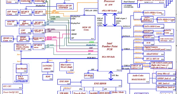
Lenovo Thinkpad T460s Bt460 Nm A421 Schematic Diagram

What Is A System Panel Connector
Lenovo Community

A Motherboard Diagram With Labels

4 4 Replacing A Motherboard Repairing And Upgrading Your Pc Book
Computer Wiring How To Connect Your Computer Wires

Motherboard Diagram Wiring Chart And Connection Guide Basics Bright Hub
A Diagram And Explanation Of Motherboard Parts And Their Functions Tom S Hardware
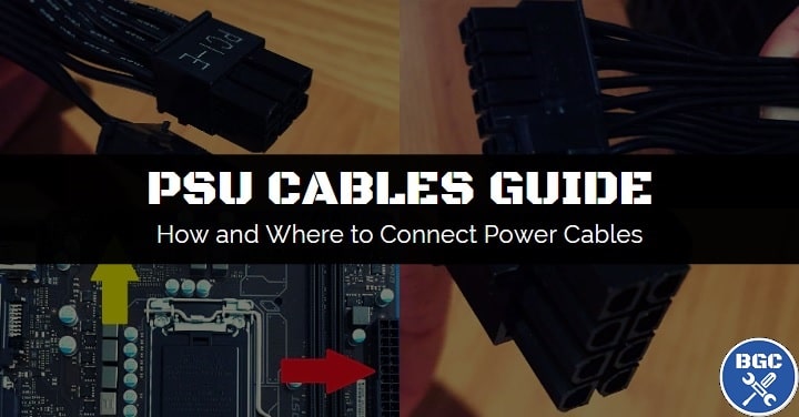
How To Connect Power Supply Cables Motherboard Diagram
What Is The Motherboard In Computer Components And Definition Of Motherboard With Diagram Concepts All

What Are Motherboard Components

Motherboard Circuit Diagram Free Vector Graphic On Pixabay
What Is A Motherboard Definition Diagram
Motherboard Power Connectors Pc Repair And Maintenance In Depth Look At Power Supply Informit
Motherboard Power Connectors Cpus Motherboards And Memory Linus Tech Tips
Motherboard Wikipedia
20 Main Motherboard Components And Their Functions

Motherboard Connections Explained Youtube
Comments
Post a Comment