39 fec phase diagram
Download scientific diagram | Fe-C phase diagram (CALPHAD.com). from publication: Thermophysical properties and structure of liquid Fe-C alloys | The paper reports experimental data on density and ... Iron Carbon Phase Diagram explanation Meenu Gupta will share all the important aspects of this Fe Carbon Phase Diagram along with her various preparation str...
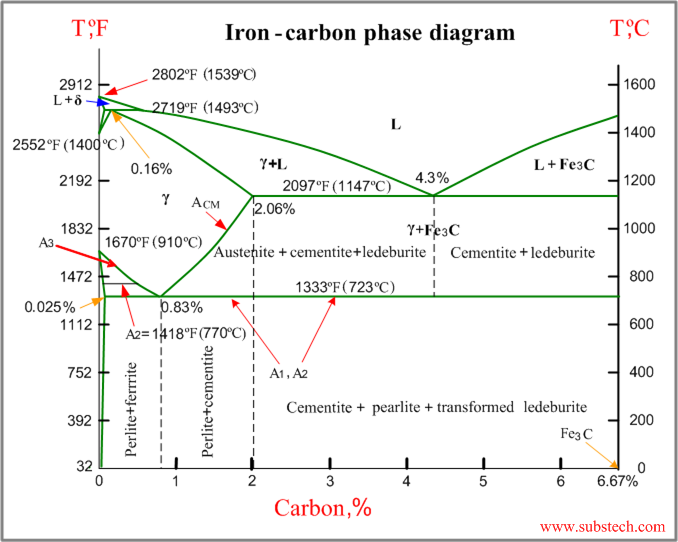
What Is Iron-Carbon Phase Diagram? Iron-Carbon(Fe-C) phase diagram. The iron carbon phases and phase diagram is slightly complex, compared with other diagrams. The horizontal axis of the Fe-C diagram shows the percentage of carbon inside the Fe-C systems. The solubility limit of carbon inside the iron is very low. So the diagram above shows up to 6.11% of carbon content which is also the solubility limit of carbon inside iron.
Fec phase diagram
Transcribed image text: Chapter 9 phase diagram > Question List Question 5 of 15 View Policies Current Attempt in Progress Question 1 1/1 Question 2 1/1 Cat Consider 1.7 kg of austenito containing 0.48 wtCcooled to below 727(13417) (a) What is the protectoid phase? How many kilograms each of totalferrite and cementite form? (c) How many kilograms each of pearlite and the protectoid phase form? Tie lines are the name given to lines that bridge the "coexistence space" in a phase diagram. In the example above the lens-shaped region between the line and the curve is a "no mans land" that separates the vapor phase compositions from the liquid phase compositions. The bi-colored line is an example of a tie line. A study of the microstructure of all steels usually starts with the metastable iron-carbon (Fe-C) binary phase diagram (Figure 1). It provides an invaluable foundation on which to build knowledge of both carbon steels and alloy steels, as well as a number of various heat treatments they are usually subjected to (hardening, annealing, etc).
Fec phase diagram. View Lecture PPT Chapter 9.18-9.20.pdf from ME MISC at Georgia State University. Iron-Carbon (Fe-C) Phase Diagram L γ + Fe3C - Eutectoid (B): γ α + Fe3C T(°C) 1600 δ L 1400 γ Phase Diagram. このサイトを検索. HOME. エリンガム図 / Ellingham diagram. セラミックス / Ceramics. Software. Solid / 水溶液 ... Phase Diagrams, 2nd ed., Vol. 1, T.B. Massalski (Ed.-in-Chief), ASM International, Materials Park, OH, 1990.) (Fe-C System) 6 C 0 Fe 3 C g g g g g g g g g g g Adapted from Fig. 9.33, Callister & Rethwisch 8e. proeutectoid Fe 3 C 60 mm Hypereutectoid steel pearlite pearlite Fe-C phase diagram
Review Fe-C phase diagram • 2 important points-Eutectoid (B): γ⇒α+Fe 3C-Eutectic (A): L ⇒γ+Fe 3C Fe 3 C (cementite) 1600 1400 1200 1000 800 600 400 0 12 3 4 5 66.7 L γ (austenite) γ+L γ+Fe 3C α+Fe 3C α + γ L+Fe 3C δ (Fe) C o, wt% C 1148°C T(°C) α 727°C = Teutectoid A R S 4.30 Result: Pearlite = alternating layers of αand Fe ... T-T-T diagram The relation between temperature and time for the formation of a phase is given by T-T-T or temp time transformation diagrams also known as isothermaltransformation diagram. A typical T-T-T diagram is shown below. The phases formed on isothermal holding at a given temp for a certain period of time are indicated. Start studying Fe-FeC Phase Diagram. Learn vocabulary, terms, and more with flashcards, games, and other study tools. This iron carbon phase diagram is plotted with the carbon concentrations by weight on the X-axis and the temperature scale on the Y-axis. The carbon in iron is an interstitial impurity. The alloy may form a face centred cubic (FCC) lattice or a body centred cubic (BCC) lattice. It will form a solid solution with α, γ, and δ phases of iron.
Nov 4, 2018 - A study of the microstructure of all steels usually starts with the metastable Fe-C binary phase diagram. It provides an invaluable foundation on which to build knowledge of both carbon steels and alloy steels, as well as a number of various heat treatments they are usually subjected to (hardening, annealing, etc). The Fe-C phase diagram is a fairly complex one, but we will only consider the steel and cast iron part of the diagram, up to 6.67% Carbon. 3. Fe - C Equilibrium Diagram 4. Phases in Fe-C Phase Diagram • α-ferrite - solid solution of C in BCC Fe • Stable form of iron at room temperature. This Project calculated the behavior of the FeC system under the effects of 120, 200 and 500 kOe magnetic fields. The phase diagram of FeC were generated for the previously mentioned magnetic fields using the ThermoCalc software. The lower portion of the diagram was pushed up while the lower portion moved down compressing the phase diagram of FeC. The percentage of carbon at eutectic point in Fe-C phase diagram is? a) 2.1 b) 4.3 c) 0.83 d) 0.02. Answer: b Clarification: The lowest melting alloy, the Fe-4.3% C alloy is called eutectic cast iron. This is a single-phase liquid (100%) of 4.3% carbon at the eutectic temeprature 1150 o C. 7. The percentage of carbon at eutectoid point in Fe-C ...
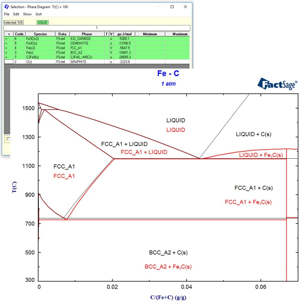
Example For A Factsage Calculation Of A Non Equilibrium Process Gtt Technologies
phase diagrams of the Fe-C system, especially on the Fe-rich side, are known much better than any other binary systems with similar complexity. However, there are still substantial areas where the phase diagram has not been well established---in the temperature, composition, and pressure ranges not related directly to iron and ...
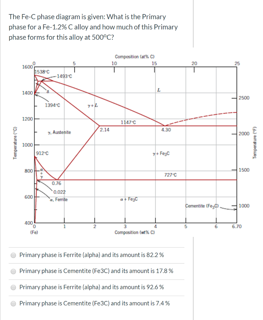
Solved The Fe C Phase Diagram Is Given What Is The Primary Chegg Com
Transcribed image text: Q.3b. With the help of the Fe-C phase diagram: ture/ composition from i) Define eutectic transformation. Cite example of one eutectic temperatu the Fe-C phase diagram.

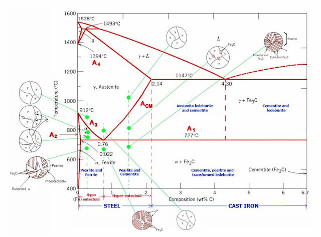
강철01 Steel Phases And Structures 소중한 우리 인생
Fig 4 Portion of Fe-C phase diagram in hyper eutectoid region. The line on the diagram named ‘Acm’ defines the solubility limit for C in austenite. It can be seen that at 820 deg C, this line gives a point at 1 % C, which is the maximum amount of C that can be dissolved in austenite at 820 deg C. Alloys having percent C compositions to the ...

Metastable Iron Carbon Fe C Phase Diagram
Diagram Fe-Fe3C yaitu diagram yang menampilkan hubungan antara temperatur dan kandungan karbon (%C) selama pemanasan lambat. Dari diagram fasa tersebut dapat diperoleh hasil yaitu berupa informasi penting yaitu antara lain : 1. Fasa yang terjadi pada komposisi dan temperatur yang berbeda dengan pendinginan lambat. 2.
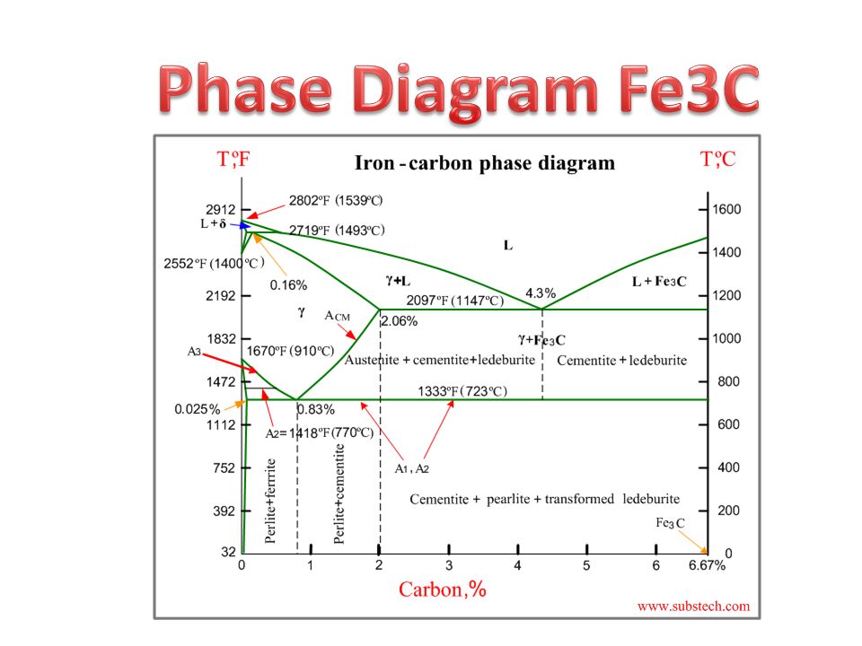
Phase Diagram Fe3c Ppt Video Online Download
The minimum temperature at which liquid phase can exist is also the maximum temperature at which only solid p… View the full answer Transcribed image text : Consider the following Fe-C phase diagram: 1600 1538°C 1493°C L 1400 1394°C Y+L 1200 1147°C 2.14 4.30 7.
2
Fe-C Phase Diagram. Fe-C Phase Diagram Pure Iron 1538°C • Upon heating pure Iron experiences two Melts changes in crystal structure. or α iron. • At room temperature it exists as ferrite, δ Ferrite 1394°C - BCC crystal structure BCC - mostly iron with a little carbon - relatively soft γ iron • When we heat it to 912°C it ...

Draw Fe Fe3c Diagram And Explain Euctetoid Eutectic And Peritectic Transformations In Fe Fe3c
T-T-T Diagram Figure 5-7 Isothermal transformation diagram (T-T-T diagram) for eutectoid composition steel. Structures resulting from transformation at various temperatures are shown as insets. (Courtesy of United States Steel Corp., Pittsburgh, PA.)

Color Online Bulk Fe C Phase Diagram With Arrows Indicating The Download Scientific Diagram
Figure 3 shows a section of the Fe-C phase diagram and Figure 4 shows an isopleth for the Fe-C-Cr ternary phase diagram for 5% Cr. In Figure 3, austenite saturation with carbon does not occur at ...
Iron Carbon Phase Diagram Explained With Graphs
• The Fe-C phase diagram is a fairly complex one, but we will only consider the steel and cast iron part of the diagram, up to 6.67% Carbon. 3. Fe – C Equilibrium Diagram 4. ©2003 Brooks/Cole, a division of Thomson Learning, Inc. Thomson Learning ™ is a trademark used herein under license. Figure 12.33 The iron-carbon phase diagram ...

Thermodynamic Calculations Of Fec Under Magnetic Field The Phase Diagram Of Fec Were Generated For
Phase Diagram for Fe-C-X. Move the mouse over the phase diagram to view temperature and composition at any point. View micrographs for the Fe-C-X system. List all systems with phase diagrams. 2004-2021 University of Cambridge. Except where otherwise noted, content is licensed under a
Example For A Factsage Calculation Of A Non Equilibrium Process Gtt Technologies
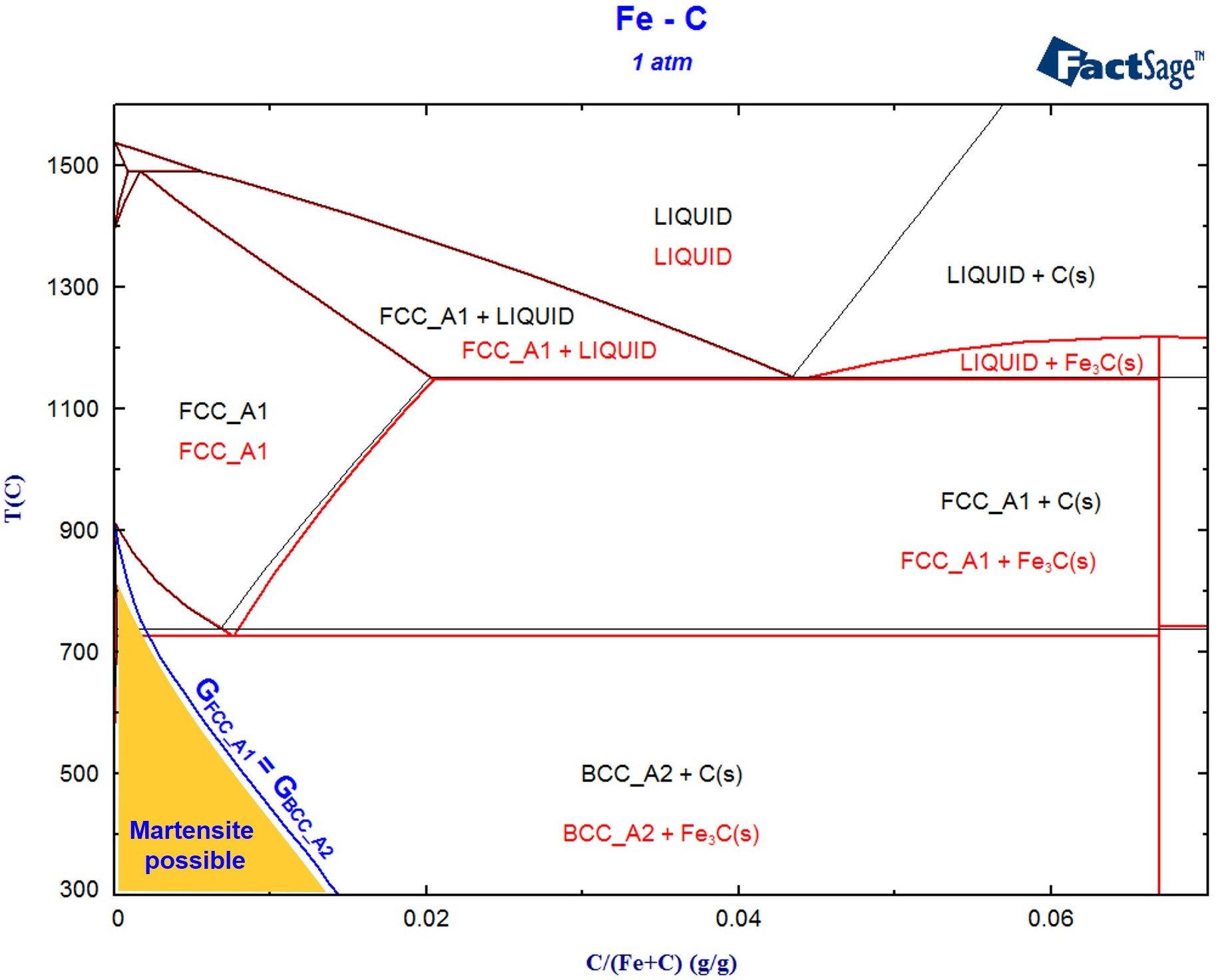
A critical review of published data provides a fairly accurate knowledge of the thermodynamic properties of all of the phases of the system Fe-C that are stable or metastable at atmospheric pressure. Selected data are shown as tables and equations. A proposed phase diagram differs only slightly from others recently published but has the following features. Peritectic compositions and the α-γ ...

Solved By Using The Iron Carbon Fe C Phase Diagram Chegg Com
The simplest phase diagrams are pressure-temperature diagrams of a single simple substance, such as water.The axes correspond to the pressure and temperature.The phase diagram shows, in pressure-temperature space, the lines of equilibrium or phase boundaries between the three phases of solid, liquid, and gas.. The curves on the phase diagram show the points where the free energy (and other ...

File Fe C Diagram Metastable Png Wikimedia Commons
A study of the microstructure of all steels usually starts with the metastable iron-carbon (Fe-C) binary phase diagram (Figure 1). It provides an invaluable foundation on which to build knowledge of both carbon steels and alloy steels, as well as a number of various heat treatments they are usually subjected to (hardening, annealing, etc).

The Pillars Curriculum For Chemical Engineering
Tie lines are the name given to lines that bridge the "coexistence space" in a phase diagram. In the example above the lens-shaped region between the line and the curve is a "no mans land" that separates the vapor phase compositions from the liquid phase compositions. The bi-colored line is an example of a tie line.

State Of Matter Bioorga
Transcribed image text: Chapter 9 phase diagram > Question List Question 5 of 15 View Policies Current Attempt in Progress Question 1 1/1 Question 2 1/1 Cat Consider 1.7 kg of austenito containing 0.48 wtCcooled to below 727(13417) (a) What is the protectoid phase? How many kilograms each of totalferrite and cementite form? (c) How many kilograms each of pearlite and the protectoid phase form?

Phase Diagram Wikiwand
2

The Iron Carbon Phase Diagram
Tikalon Blog By Dev Gualtieri

Muddiest Point Phase Diagrams Iv Fe Fe3c Steel Calculations Youtube
2
2

Pin On Metallurgy Welding Engineer
Iron Carbon Phase Diagram Substech
1
2

Thermodynamics And Phase Diagram Of The Fe C System Semantic Scholar
Phase Diagram Array
Solidification Of Steels

Fe C Phase Diagram Calphad Com Download Scientific Diagram
Why Is There No Beta Phase Diagram In The Iron Iron Carbide Diagram Quora
2
Iron Carbon Phase Diagram
1
2
2
Iron Iron Carbide Phase Diagram Example
Nglos324 Carbonsteel

Tpce Mech Books Iron Carbon Phase Diagram Or Equilibrium Diagram
Comments
Post a Comment